
第1页 / 共22页
试读已结束,还剩21页,您可下载完整版后进行离线阅读
THE END
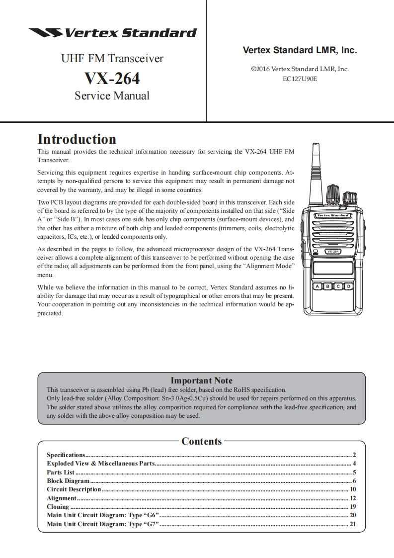
S Vertex StandardVertex Standard LMR,Inc.UHF FM Transceiver2016 Vertex Standard LMR,Inc.VX-264EC127U90EService ManualIntroductionThis manual provides the technical information necessary for servicing the VX-264 UHF FMTransceiver.Servicing this equipment requires expertise in handing surface-mount chip components.At-tempts by non-qualified persons to service this equipment may result in permanent damage notcovered by the warranty,and may be illegal in some countries.Two PCB layout diagrams are provided for each double-sided board in this transceiver.Each sideof the board is referred to by the type of the majority of components installed on that side("SideA"or"Side B").In most cases one side has only chip components (surface-mount devices),andthe other has either a mixture of both chip and leaded components(trimmers,coils,electrolyticcapacitors,ICs,etc.)or leaded components only.As described in the pages to follow,the advanced microprocessor design of the VX-264 Trans-x284】ceiver allows a complete alignment of this transceiver to be performed without opening the caseofthe radio,all adjustments can be performed from the front panel,using the"Alignment Mode"menu.While we believe the information in this manual to be correct,Vertex Standard assumes no li-ABDability for damage that may occur as a result oftypographical or other errors that may be present.Your cooperation in pointing out any inconsistencies in the technical information would be ap-preciated.Important NoteThis transceiver is assembled using Pb(lead)free solder,based on the RoHS specification.Only lead-free solder(Alloy Composition:Sn-3.0Ag-0.5Cu)should be used for repairs performed on this apparatus.The solder stated above utilizes the alloy composition required for compliance with the lead-free specification,andany solder with the above alloy composition may be usedContentsSpecifications...Exploded View Miscellaneous Parts...4Parts List.5Block Diagram.....Circuit DescriptionAlignment12Cloning.....19Main Unit Circuit Diagram:Type "G6".20Main Unit Circuit Diagram:Type“G7”21


请登录后查看评论内容