
第1页 / 共66页
试读已结束,还剩65页,您可下载完整版后进行离线阅读
THE END
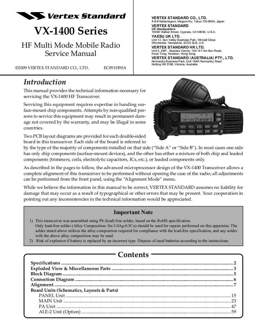
Vertex StandardVERTEX STANDARD CO.,LTD.4-8-8 Nakameguro,Meguro-Ku,Tokyo 153-8644,JapanVERTEX STANDARDVX-1400 SeriesUS Headquarters10900 Walker Street,Cypress,CA 90630,U.S.A.YAESU UK LTD.Unit 12,Sun Valley Business Park,Winnall CloseHF Multi Mode Mobile RadioWinchester,Hampshire,SO23 OLB,U.K.VERTEX STANDARD HK LTD.Service ManualUnit 5,20/F.,Seaview Centre,139-141 Hoi Bun Road,Kwun Tong,Kowloon,Hong KongVERTEX STANDARD(AUSTRALIA)PTY.,LTD.rmanbyess Park,Unit 14/45 Normanby RoadNotting Hill 3168,Victoria,Australia2009 VERTEX STANDARD CO.,LTD.EC091H90AIntroductionThis manual provides the technical information necessary forservicing the VX-1400 HF Transceiver.Servicing this equipment requires expertise in handing sur-face-mount chip components.Attempts by non-qualified per-sons to service this equipment may result in permanent dam-age not covered by the warranty,and may be illegal in somecountries.PmP四POP四PTwo PCBlayout diagrams are provided for each double-sidedboard in this transceiver.Each side of the board is referred toby the type of the majority of components installed on that side("Side A"or "Side B").In most cases one sidehas only chip components(surface-mount devices),and the other has either a mixture of both chip and leadedcomponents(trimmers,coils,electrolytic capacitors,ICs,etc.),or leaded components only.As described in the pages to follow,the advanced microprocessor design of the VX-1400 Transceiver allows acomplete alignment of this transceiver to be performed without opening the case of the radio;all adjustmentscan be performed from the front panel,using the "Alignment Mode"menu.While we believe the information in this manual to be correct,VERTEX STANDARD assumes no liability fordamage that may occur as a result of typographical or other errors that may be present.Your cooperation inpointing out any inconsistencies in the technical information would be appreciated.Important Note1)This transceiver was assembled using Pb(lead)free solder,based on the RoHS specification.Only lead-free solder(Alloy Composition:Sn-3.0Ag-0.5Cu)should be used for repairs performed on this apparatus.Thesolder stated above utilizes the alloy composition required for compliance with the lead-free specification,and any solderwith the above alloy composition may be used.2)Risk of explosion if battery is replaced by an incorrect type.Dispose of used batteries according to the instructions.ContentsSpectications.................................................................2Exploded View Miscellaneous Parts ..................Block Diagram…35Connection Diagram....6Alignment…7Board Units(Schematics,Layouts Parts)PANEL Unit............15MAIN Unit.23PA Unit ...47ALE-2 Unit (Option).59


请登录后查看评论内容