
第1页 / 共86页
试读已结束,还剩85页,您可下载完整版后进行离线阅读
THE END
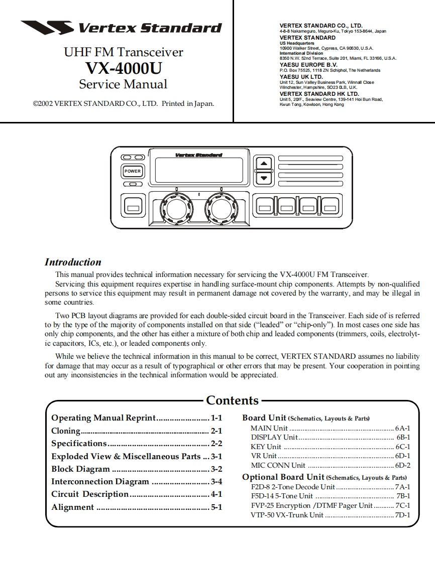
Vertex StandardVERTEX STANDARD CO.,LTD.4-8-8 Nakameguro,Meguro-Ku,Tokyo 153-8644,JapanVERTEX STANDARDUS HeadquartersUHF FM Transceiver10900 Walker Street,Cypress,CA90630.U.SA8350 N.W.52nd Terrace.Suite 201,Miami,FL33166.U.SA.VX-4000UYAESU EUROPE B.V.P.O.Box 75525,1118 ZN Schiphol,The NetherlandsYAESU UK LTD.Service ManualUnit 12,Sun Valley Business Park,Winnall CloseWinches ter,Hampshire,S023 0LB,U.K.VERTEX STANDARD HK LTD.Unit 5,20/F.,Seaview Centre,139-141 Hoi Bun Road,@2002 VERTEX STANDARD CO.,LTD.Printed in Japan.Kwun Tong.Kowloon,Hong KongIntroductionThis manual provides technical information necessary for servicing the VX-4000U FM Transceiver.Servicing this equipment requires expertise in handling surface-mount chip components.Attempts by non-qualifiedpersons to service this equipment may result in permanent damage not covered by the warranty,and may be illegal insome countries.Two PCB layout diagrams are provided for each double-sided circuit board in the Transceiver.Each side of is referredto by the type of the majority of components installed on that side ("leaded"or"chip-only").In most cases one side hasonly chip components,and the other has either a mixture of both chip and leaded components(trimmers,coils,electrolyt-ic capacitors,ICs,etc.),or leaded components only.While we believe the technical information in this manual to be correct,VERTEX STANDARD assumes no liabilityfor damage that may occur as a result of typographical or other errors that may be present.Your cooperation in pointingout any inconsistencies in the technical information would be appreciated.Contents-Operating Manual Reprint.....1-1Board Unit (Schematics,Layouts Parts)ClOning2-1MAINUnit.6A-1DISPLAY Unit.…6B-1Specifications.….2-2KEYUnit.6C-1Exploded View Miscellaneous Parts ...3-1VR Unit.6D-1Block Diagram3-2MIC CONN Unit…6D-2Interconnection Diagram..3-4Optional Board Unit (Schematics,Layouts Parts)F2D-82-Tone Decode Unit......................A-1Circuit Description.....................4-1F5D-145-Tone Unit7B-1Alignment.5-1FVP-25 Encryption /DTMF Pager Unit...........C-1VTP-50 VX-Trunk Unit..D-1


请登录后查看评论内容