
第1页 / 共45页
试读已结束,还剩44页,您可下载完整版后进行离线阅读
THE END
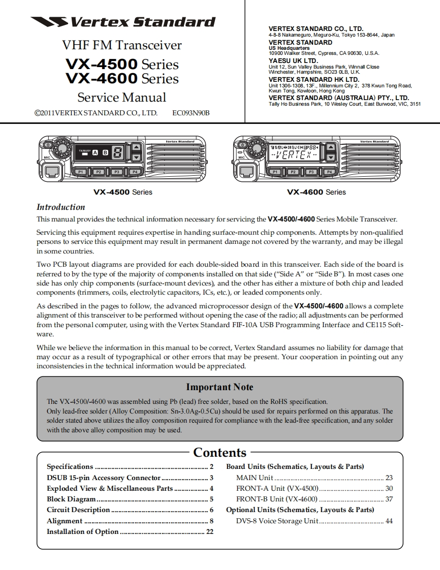
SVertex StandardVERTEX STANDARD CO.,LTD.4-8-8 Nakameguro,Meguro-Ku,Tokyo 153-8644,JapanVHF FM TransceiverVERTEX STANDARDUS Headquarters10900 Waiker Street,Cypress,CA 90630,U.S.A.VX-4500 SeriesYAESU UK LTD.Unit 12,Sun Valley Business Park,Winnall CloseWinchester,Hampshire,S023 OLB,U.K.VX-4600 SeriesVERTEX STANDARD HK LTD.Unit 1306-1308,13F.,Millennium City 2,378 Kwun Tong Road,Kwun Tong.Kowloon,Hong KongService ManualVERTEX STANDARD(AUSTRALIA)PTY..LTD.Tally Ho Business Park,10 Wesley Court,East Burwood,VIC,3151C2011VERTEXSTANDARD CO.,LTD.EC093N90B&L请6,dM日P88…VERTEXP1P2 P3P4P1VX-4500 SeriesVX-4600 SeriesIntroductionThis manual provides the technical information necessary for servicing the VX-4500/-4600 Series Mobile Transceiver.Servicing this equipment requires expertise in handing surface-mount chip components.Attempts by non-qualifiedpersons to service this equipment may result in permanent damage not covered by the warranty,and may be illegalin some countries.Two PCB layout diagrams are provided for each double-sided board in this transceiver.Each side of the board isreferred to by the type of the majority of components installed on that side("Side A"or"Side B").In most cases oneside has only chip components(surface-mount devices),and the other has either a mixture of both chip and leadedcomponents(trimmers,coils,electrolytic capacitors,ICs,etc.),or leaded components only.As described in the pages to follow,the advanced microprocessor design of the VX-4500/-4600 allows a completealignment of this transceiver to be performed without opening the case of the radio;all adjustments can be performedfrom the personal computer,using with the Vertex Standard FIF-10A USB Programming Interface and CE115 Soft-ware.While we believe the information in this manual to be correct,Vertex Standard assumes no liability for damage thatmay occur as a result of typographical or other errors that may be present.Your cooperation in pointing out anyinconsistencies in the technical information would be appreciated.Important NoteThe VX-4500/-4600 was assembled using Pb (lead)free solder,based on the RoHS specification.Only lead-free solder(Alloy Composition:Sn-3.0Ag-0.5Cu)should be used for repairs performed on this apparatus.Thesolder stated above utilizes the alloy composition required for compliance with the lead-free specification,and any solderwith the above alloy composition may be used.ContentsSpecifications.2Board Units(Schematics,Layouts Parts)DSUB 15-pin Accessory Connector......3MAIN Unit.23Exploded View Miscellaneous Parts ...............4FRONT-A Unit (VX-4500).............30Bl0 ck Diagram…5ERONT-B Unit (VX-4600)...37Circuit Description......6Optional Units(Schematics,Layouts Parts)Alighment.8DVS-8 Voice Storage Unit.....................44Installation of Option.....22

请登录后查看评论内容