
第1页 / 共2页
试读已结束,还剩1页,您可下载完整版后进行离线阅读
THE END
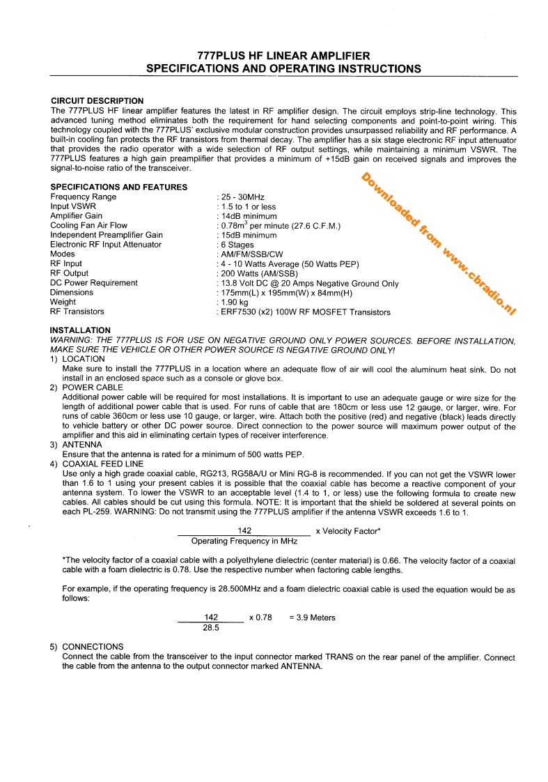
777PLUS HF LINEAR AMPLIFIERSPECIFICATIONS AND OPERATING INSTRUCTIONSCIRCUIT DESCRIPTIONThe 777PLUS HF linear amplifier features the latest in RF amplifier design.The circuit employs strip-line technology.Thisadvanced tuning method eliminates both the requirement for hand selecting components and point-to-point wiring.Thistechnology coupled with the 777PLUS'exclusive modular construction provides unsurpassed reliability and RF performance.Abuilt-in cooling fan protects the RF transistors from thermal decay.The amplifier has a six stage electronic RF input attenuatorthat provides the radio operator with a wide selection of RF output settings,while maintaining a minimum VSWR.The777PLUS features a high gain preamplifier that provides a minimum of +15dB gain on received signals and improves thesignal-to-noise ratio of the transceiver.0】SPECIFICATIONS AND FEATURESFrequency Range:25-30MHzInput VSWR1.5 to 1 or lessAmplifier Gain14dB minimumadeCooling Fan Air Flow0.78m per minute (27.6 C.F.M.)Independent Preamplifier Gain15dB minimumElectronic RF Input Attenuator6 StagesomModesAM/FM/SSB/CWRF Input4-10 Watts Average(50 Watts PEP)RF Output:200 Watts(AM/SSB)】DC Power Requirement13.8 Volt DC 20 Amps Negative Ground OnlyDimensions:175mm(L)X195mmW)×84mm(H)Weight:1.90kg.cbradio.nlRF TransistorsERF7530(x2)100W RF MOSFET TransistorsINSTALLATIONWARNING:THE 777PLUS IS FOR USE ON NEGATIVE GROUND ONLY POWER SOURCES.BEFORE INSTALLATION.MAKE SURE THE VEHICLE OR OTHER POWER SOURCE IS NEGATIVE GROUND ONLY!1)LOCATIONMake sure to install the 777PLUS in a location where an adequate flow of air will cool the aluminum heat sink.Do notinstall in an enclosed space such as a console or glove box.2)POWER CABLEAdditional power cable will be required for most installations.It is important to use an adequate gauge or wire size for thelength of additional power cable that is used.For runs of cable that are 180cm or less use 12 gauge,or larger,wire.Forruns of cable 360cm or less use 10 gauge,or larger,wire.Attach both the positive (red)and negative (black)leads directlyto vehicle battery or other DC power source.Direct connection to the power source will maximum power output of theamplifier and this aid in eliminating certain types of receiver interference3)ANTENNAEnsure that the antenna is rated for a minimum of 500 watts PEP4)COAXIAL FEED LINEUse only a high grade coaxial cable,RG213.RG58A/U or Mini RG-8 is recommended.If you can not get the VSWR lowerthan 1.6 to 1 using your present cables it is possible that the coaxial cable has become a reactive component of yourantenna system.To lower the VSWR to an acceptable level (1.4 to 1,or less)use the following formula to create newcables.All cables should be cut using this formula.NOTE:It is important that the shield be soldered at several points oneach PL-259.WARNING:Do not transmit using the 777PLUS amplifier if the antenna VSWR exceeds 1.6 to 1.142x Velocity Factor'Operating Frequency in MHz"The velocity factor of a coaxial cable with


请登录后查看评论内容