
第1页 / 共32页
试读已结束,还剩31页,您可下载完整版后进行离线阅读
THE END
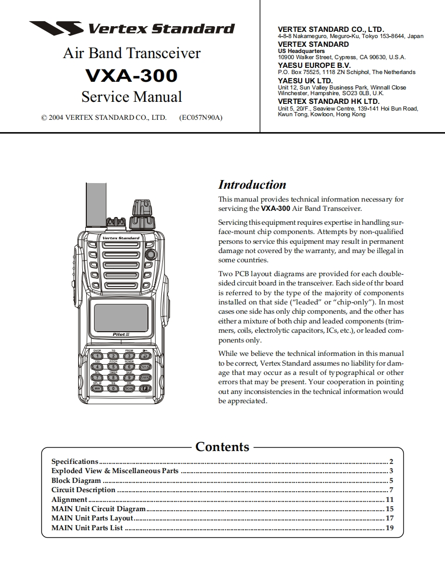
Vertex StandardVERTEX STANDARD CO.,LTD.4-8-8 Nakameguro,Meguro-Ku,Tokyo 153-8644,JapanVERTEX STANDARDAir Band TransceiverUS Headquarters10900 Walker Street,Cypress.CA 90630.U.S.A.YAESU EUROPE B.V.VXA-300P.O.Box 75525,1118 ZN Schiphol,The NetherlandsYAESU UK LTD.Unit 12,Sun Valley Business Park,Winnall CloseService ManualWinchester,Hampshire,SO23 OLB,U.KVERTEX STANDARD HK LTD.Unit 5,20/F.,Seaview Centre,139-141 Hoi Bun Road,2004 VERTEX STANDARD CO.,LTD.(EC057N90A)Kwun Tong,Kowloon,Hong KongIntroductionThis manual provides technical information necessary forservicing the VXA-300 Air Band Transceiver.Servicing thisequipment requires expertise in handling sur-face-mount chip components.Attempts by non-qualifiedpersons to service this equipment may result in permanentdamage not covered by the warranty,and may be illegal insome countries.Two PCB layout diagrams are provided for each double-sided circuit board in the transceiver.Each side of thr boardis referred to by the type of the majority of componentsinstalled on that side("leaded"or"chip-only").In mostcases one side has only chip components,and the other haseither a mixture of both chip and leaded components(trim-mers,coils,electrolytic capacitors,ICs,etc.),or leaded com-ponents only.While we believe the technical information in this manualto be correct,Vertex Standard assumes no liability for dam-age that may occur as a result of typographical or othererrors that may be present.Your cooperation in pointingout any inconsistencies in the technical information wouldbe appreciated.ContentsSpecifications.........2Exploded View Miscellaneous Parts.3Block Diagram...5Circuit Description...........7Alignment......11MAIN Unit Circuit Diagram..15MAIN Unit Parts Layout......17MAIN Unit Parts List .....19


请登录后查看评论内容