
第1页 / 共27页
试读已结束,还剩26页,您可下载完整版后进行离线阅读
THE END
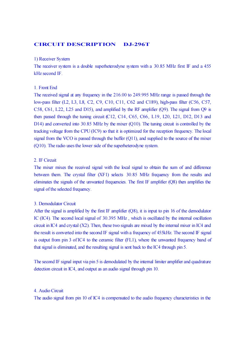
CIRCUIT DESCRIPTION DJ-296T1)Receiver SystemThe receiver system is a double superheterodyne system with a 30.85 MHz first IF and a 455kHz second IF.1.Front EndThe received signal at any frequency in the 216.00 to 249.995 MHz range is passed through thelow-pass filter (L2,L3,L8,C2,C9,C10,C11,C62 and C189),high-pass filter (C56,C57,C58,C61,L22,L25 and D15),and amplified by the RF amplifier (Q9).The signal from Q9 isthen passed through the tuning circuit (C12,C14,C65,C66,L19,120,121,D12,D13 andD14)and converted into 30.85 MHz by the mixer (Q10).The tuning circuit is controlled by thetracking voltage fom the CPU(IC9)so that it is optimized for the reception frequency.The localsignal from the VCO is passed through the buffer(Q11),and supplied to the source of the mixer(Q10).The radio uses the lower side of the superheterodyne system.2.IF CircuitThe mixer mixes the received signal with the local signal to obtain the sum of and differencebetween them.The crystal filter (XF1)selects 30.85 MHz frequency from the results andeliminates the signals of the unwanted frequencies.The first IF amplifier (Q8)then amplifies thesignal ofthe selected frequency.3.Demodulator CircuitAfter the signal is amplified by the first IF amplifier (Q8),it is input to pin 16 of the demodulatorIC (IC4).The second local signal of 30.395 MHz,which is oscillated by the intemal oscillationcircuit in IC4 and crystal (X2).Then,these two signals are mixed by the internal mixer in IC4 andthe result is converted into the second IF signal with a frequency of 455kHz The second IF signalis output from pin 3 ofIC4 to the ceramic filter (FL1),where the unwanted frequency band ofthat signal is eliminated,and the resulting signal is sent back to the IC4 through pin 5.The second IF signal input via pin 5 is demodulated by the intemal limiter amplifier and quadraturedetection circuit in IC4,and output as an audio signal through pin 10.4.Audio CircuitThe audio signal from pin 10 of IC4 is compensated to the audio frequency characteristics in the


请登录后查看评论内容