
第1页 / 共2页
试读已结束,还剩1页,您可下载完整版后进行离线阅读
THE END
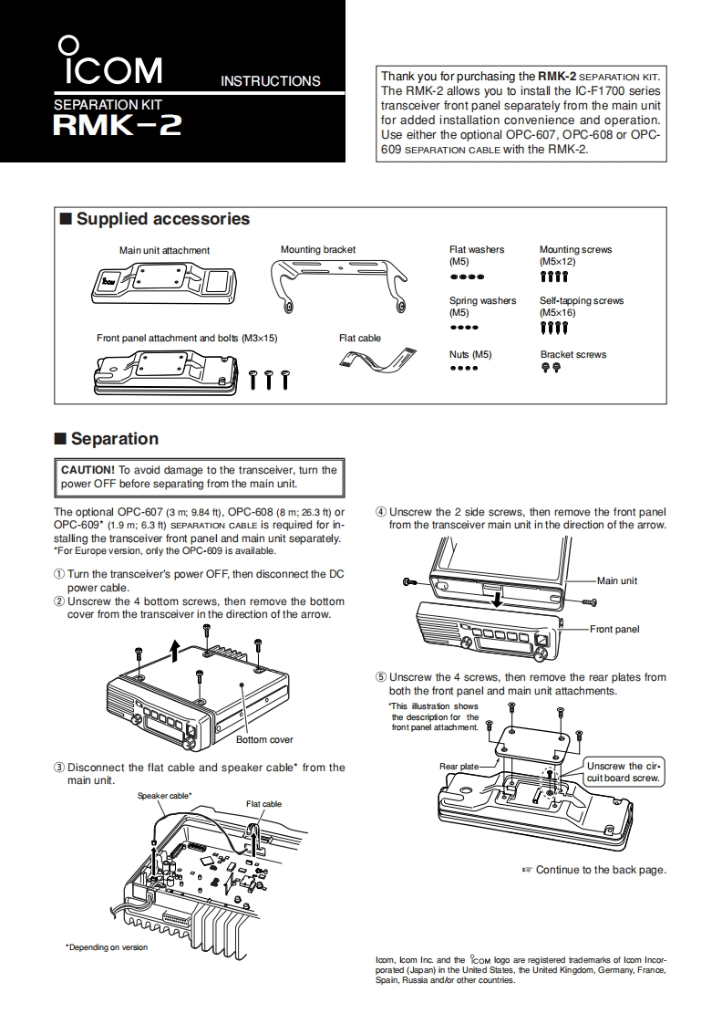
INSTRUCTIONSThank you for purchasing the RMK-2 SEPARATION KIT.The RMK-2 allows you to install the IC-F1700 seriesSEPARATION KITtransceiver front panel separately from the main unitRMK-2for added installation convenience and operationUse either the optional OPC-607,OPC-608 or OPC-609 SEPARATION CABLE with the RMK-2.Supplied accessoriesMain unit attachmentMounting bracketFlat washersMounting screwsM5)(M5x12)都步准●TTT行Spring washersSelf-tapping screwsM5)(M5x16)●●●●ooo0Front panel attachment and bolts (M3x15)月at cableNuts (M5)Bracket screws香香香香孕9TTT■SeparationCAUTION!To avoid damage to the transceiver,turn thepower OFF before separating from the main unit.The optional OPC-607 (3 m;9.84 ft),OPC-608(8 m;26.3 ft)or4 Unscrew the 2 side screws,then remove the front panelOPC-609*(1.9 m:6.3 ft)SEPARATION CABLE is required for in-from the transceiver main unit in the direction of the arrow.stalling the transceiver front panel and main unit separately."For Europe version,only the OPC-609 is available.Turn the transceiver's power OFF,then disconnect the DC-Main unitpower cable.(2Unscrew the 4 bottom screws.then remove the bottom0cover from the transceiver in the direction of the arrow.Front panel5 Unscrew the 4 screws.then remove the rear plates fromboth the front panel and main unit attachments."This illustrafion showsthe description for thefront panel attachment.Bottom cover3 Disconnect the flat cable and speaker cable*from theRear plateUnscrew the cirmain unit.cuit board screw.Speaker cableFlat cableContinue to the back page.*Depending on versionloom,lcom Inc.and the CoM logo are registered trademarks of loom Incor-ngom.mno.

请登录后查看评论内容