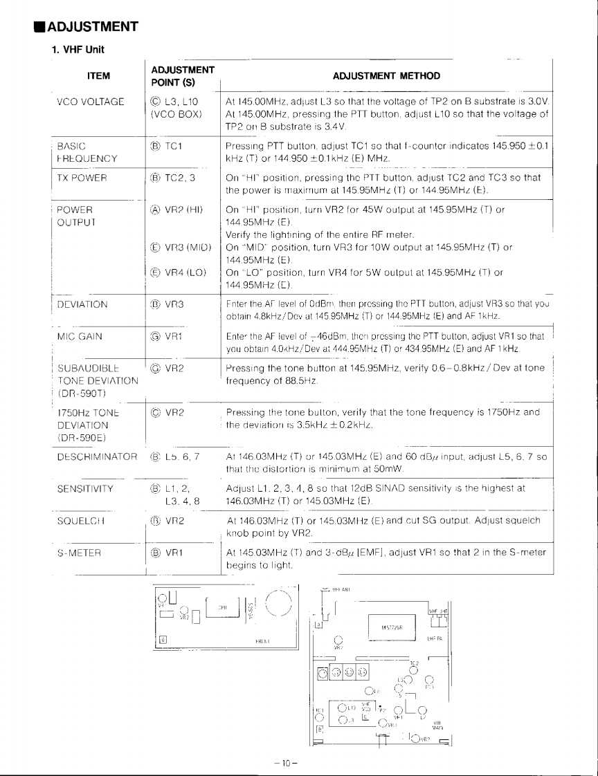
■ADJUSTMENT1.VHF UnitITEMADJUSTMENTPOINT(S)ADJUSTMENT METHODVCO VOLTAGE⊙L3.L10At 145.00MHz,adjust L3 so that the voltage of TP2 on B substrate is 3.0V.(VCO BOX)At 145.00MHz,pressing the PTT button,adjust L10 so that the voltage ofTP2 on B substrate is 3.4V.BASIC®TC1Pressing PTT button.adjust TC1 so that f-counter indicates 145.950 +0.1FREQUENCYkHz (T)or 144.950 0.1kHz (E)MHz.TX POWER⑧TC2,3On"HI"position,pressing the PTT button,adjust TC2 and TC3 so thatthe power is maximum at 145.95MH2(T)or 144.95MHZ(E)POWERVR2 (HI)On "HI"position,turn VR2 for 45W oulput at 145.95MHz (T)orOUTPUT144.95MHz{E).Verify the lightining of the entire RF meter.E VR3 (MID)On "MID"position,turn VR3 for 10W output at 145.95MHz (T)or144.95MHzE).€VR4LO)On "LO"position,turn VR4 for 5W output at 145.95MHZ (T)or144.95MHz(C).DEVIATION⑧VR3Enter the Af level of OdBm,then prossing the PTT button,adjust VR3 so that youobtain 4.8kHz/Dov at 145.95MHz (T)or 144.95MHz (E)and AF 1kHz.MIC GAIN©VR1Enter the AF level of -46dBm.thon pressing the PTT bulton,adjust VR1 so thatyou obtain 4.0

请登录后查看评论内容