
第1页 / 共13页
试读已结束,还剩12页,您可下载完整版后进行离线阅读
THE END
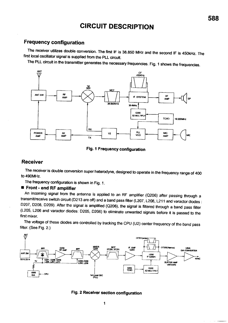
588CIRCUIT DESCRIPTIONFrequency configurationThe receiver utilizes double conversion.The first IF is 38.850 MHz and the second IF is 450kHz.Thefirst local oscillator signal is supplied from the PLL circuit.The PLL circuit in the transmitter generates the necessary frequencies.Fig.1 shows the frequencies.ANT4幻灯女ANT SWREAMPIF SYSTEMAF384M收C200程HULTPLYTCXO19.200MRXPOWERLAMPTXFlg.1 Frequency conflgurationReceiverThe receiver is double conversion super heterodyne,designed to operate in the frequency range of 400to 490MHz.The frequency configuration is shown in Fig.1.Front-end RF amplifierAn incoming signal from the antenna is applied to an RF amplifier(Q206)after passing through atransmit/receive switch circuit(D213 are off)and a band pass fitter(L207,L208,L211 and varactor diodes:D207.D208,D209).After the signal is amplified(Q206),the signal is filtered through a band pass filter(L205.L206 and varactor diodes:D205,D206)to eliminate unwanted signals before it is passed to thefirst mixer.The voltage of these diodes are controlled by tracking the CPU(U2)center frequency of the band passfilter.(See Fig.2.)CF201(widoExw200.201ECF200(Narrow)U505OA CONVERTERANT SWwHC180200没MULTIPLYFig.2 Receiver sectlon configuration

请登录后查看评论内容