
第1页 / 共6页
试读已结束,还剩5页,您可下载完整版后进行离线阅读
THE END
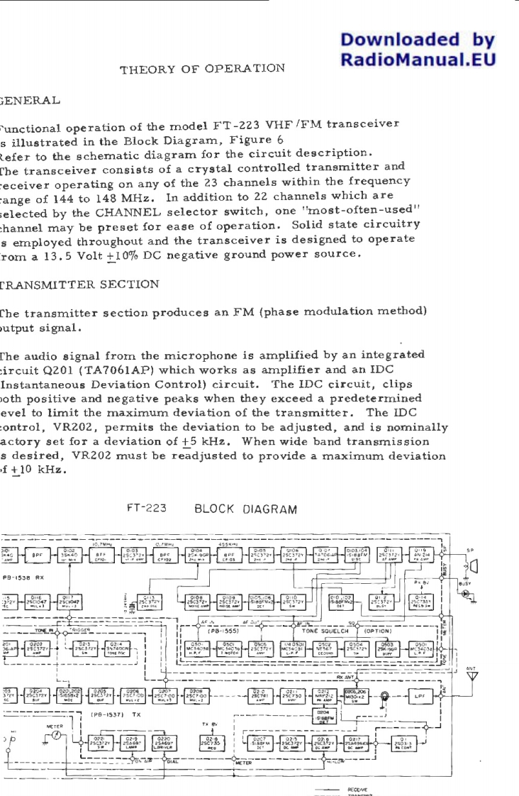
Downloaded byTHEORY OF OPERATIONRadioManual.EUENERALunctional operation of the model FT-223 VHF/FM transceivers illustrated in the Block Diagram,Figure 6efer to the schematic diagram for the circuit description.he transceiver consists of a crystal controlled transmitter andeceiver operating on any of the 23 channels within the frequencyange of 144 to 148 MHz.In addition to 22 channels which areelected by the CHANNEL selector switch,one 'most-often-used"hannel may be preset for ease of operation.Solid state circuitrys employed throughout and the transceiver is designed to operaterom a 13.5 Volt +10%DC negative ground power source.RANSMITTER SECTIONChe transmitter section produces an FM(phase modulation method)utput signal.he audio signal from the microphone is amplified by an integratedircuit Q201 (TA7061AP)which works as amplifier and an IDCInstantaneous Deviation Control)circuit.The IDC circuit,clipsoth positive and negative peaks when they exceed a predeterminedevel to limit the maximum deviation of the transmitter.The IDControl,VR202,permits the deviation to be adjusted,and is nominallyactory set for a deviation of +5 kHz.When wide band transmissions desired,VR202 must be readjusted to provide a maximum deviationf +10 kHz.FT-223BLOCK DIAGRAM1P日-4538骨×2的感P8-555TONE SOUELCHP-5371TX

请登录后查看评论内容