
第1页 / 共44页
试读已结束,还剩43页,您可下载完整版后进行离线阅读
THE END
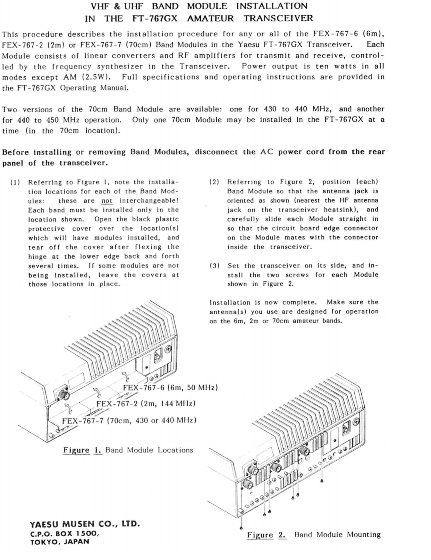
VHF UHF BAND MODULE INSTALLATIONIN THE FT-767GX AMATEUR TRANSCEIVERThis procedure describes the installation procedure for any or all of the FEX-767-6(6m),FEX-767-2 (2m)or FEX-767-7 (70cm)Band Modules in the Yaesu FT-767GX Transceiver.EachModule consists of linear converters and RF amplifiers for transmit and receive,control-led by the frequency synthesizer in the Transceiver.Power output is ten watts in allmodes except AM (2.5W).Full specifications and operating instructions are provided inthe FT-767GX Operating Manual.Two versions of the 70cm Band Module are available:one for 430 to 440 MHz,and anotherfor 440 to 450 MHz operation.Only one 70cm Module may be installed in the FT-767GX at atime (in the 70cm location).Before installing or removing Band Modules,disconnect the AC power cord from the rearpanel of the transceiver.(1)Referring to Figure 1,note the installa-(2)Referring to Figure 2,position (each)tion locations for each of the Band Mod-Band Module so that the antenna jack isules:these are not interchangeable!oriented as shown (nearest the HF antennaEach band must be installed only in thejack on the transceiver heatsink),andlocation shown.Open the black plasticcarefully slide each Module straight inprotective cover over the location(s)so that the circuit board edge connectorwhich will have modules installed,andon the Module mates with the connectortear off the cover after flexing theinside the transceiver.hinge at the lower edge back and forthseveral times.If some modules are not(3)Set the transceiver on its side,and in-being installed,leave the covers atstall the two screws for each Modulethose locations in place.shown in Figure 2.Installation is now complete.Make sure theantenna(s)you use are designed for operationon the 6m,2m or 70cm amateur bands.FEX-767-6(6m,50MHz)FEX-767-2(2m,144MHz)FEX-767-7(70cm,430or440MHz)GFigure 1.Band Module Locations000660】YAESU MUSEN CO.,LTD.C.P.0.B0X1500Figure 2.Band Module MountingTOKYO,JAPAN

请登录后查看评论内容