
第1页 / 共2页
试读已结束,还剩1页,您可下载完整版后进行离线阅读
THE END
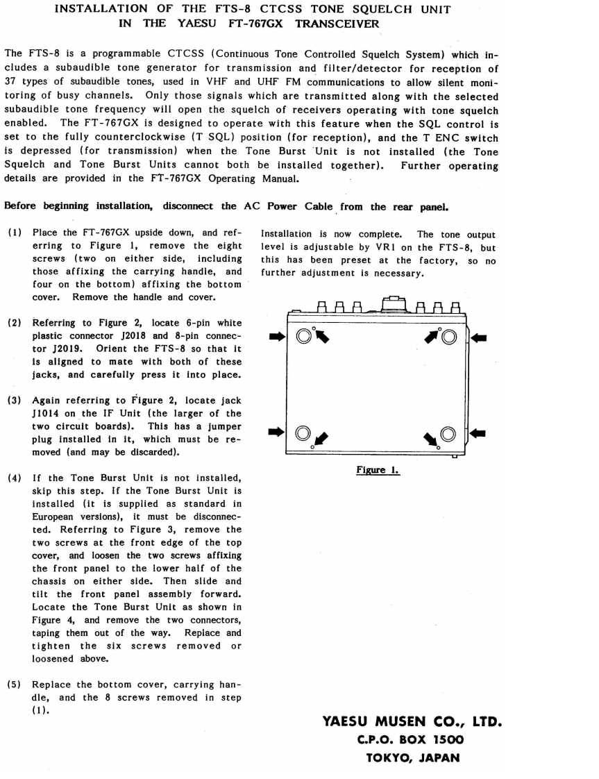
INSTALLATION OF THE FTS-8 CTCSS TONE SQUELCH UNITIN THE YAESU FT-767GX TRANSCEIVERThe FTS-8 is a programmable CTCSS (Continuous Tone Controlled Squelch System)which in-cludes a subaudible tone generator for transmission and filter/detector for reception of37 types of subaudible tones,used in VHF and UHF FM communications to allow silent moni-toring of busy channels.Only those signals which are transmitted along with the selectedsubaudible tone frequency will open the squelch of receivers operating with tone squelchenabled.The FT-767GX is designed to operate with this feature when the SQL control isset to the fully counterclockwise (T SQL)position (for reception),and the T ENC switchis depressed (for transmission)when the Tone Burst 'Unit is not installed (the ToneSquelch and Tone Burst Units cannot both be installed together).Further operatingdetails are provided in the FT-767GX Operating Manual.Before beginning installation,disconnect the AC Power Cable from the rear panel.(1)Place the FT-767GX upside down,and ref-Installation is now complete.The tone outputerring to Figure 1,remove the eight level is adjustable by VR1 on the FTS-8,butscrews (two on either side,including this has been preset at the factory,so nothose affixing the carrying handle,andfurther adjustment is necessary.four on the bottom)affixing the bottomcover.Remove the handle and cover.(2)Referring to Figure 2,locate 6-pin whiteplastic connector J2018 and 8-pin connec-tor J2019.Orient the FTS-8 so that itis aligned to mate with both of thesejacks,and carefully press it into place.(3)Again referring to Figure 2,locate jackJ1014 on the IF Unit (the larger of thetwo circuit boards).This has a jumperplug installed in it,which must be re-moved (and may be discarded).Figure 1.(4)If the Tone Burst Unit is not installed,skip this step.If the Tone Burst Unit isinstalled (it is supplied as standard inEuropean versions),it must be disconnec-ted.Referring to Figure 3,remove thetwo screws at the front edge of the topcover,and loosen the two screws affixingthe front panel to the lower half of thechassis on either side.Then slide andtilt the front panel assembly forward.Locate the Tone Burst Unit as shown inFigure 4,and remove the two connectors,taping them out of the way.Replace andtighten the six screws removed orloosened above.(5)Replace the bottom cover,carrying han-dle,and the 8 screws removed in step(1).YAESU MUSEN CO.,LTD.C.P.0.BoX1500TOKYO,JAPAN

请登录后查看评论内容