
第1页 / 共146页
试读已结束,还剩145页,您可下载完整版后进行离线阅读
THE END
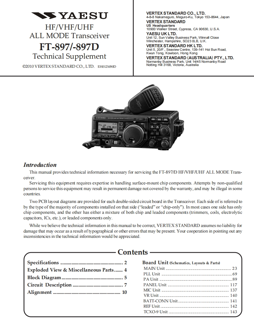
SYAESUVERTEX STANDARD CO.,LTD.4-8-8 Nakameguro,Meguro-Ku.Tokyo 153-8644,JapanVERTEX STANDARDHF/VHF/UHFUS Headquarters10900 Walker Street,Cypress,CA 90630,U.S.A.ALL MODE TransceiverYAESU UK LTD.Unit 12,Sun Valley Business Park,Winnall CloseWinchester,Hampshire,SO23 OLB,U.K.FT-897/-897DVERTEX STANDARD HK LTD.Unit 5.20/F..Seaview Centre.139-141 Hoi Bun Road.Technical SupplementKwun Tong,Kowloon,Hong KongVERTEX STANDARD(AUSTRALIA)PTY.,LTD.Normanby Business Park,Unit 14/45 Nomanby Road2010 VERTEXSTANDARD CO.,LTD.EH012M9ODNotting Hill 3168,Victoria,Australia1,176.81IntroductionThis manual provides technical information necessary for servicing the FT-897/D HF/VHF/UHF ALL MODE Trans-ceiver.Servicing this equipment requires expertise in handling surface-mount chip components.Attempts by non-qualifiedpersons to service this equipment may result in permanent damage not covered by the warranty,and may be illegal in somecountries.Two PCB layout diagrams are provided for each double-sided circuit board in the Transceiver.Each side of is referred toby the type of the majority of components installed on that side ("leaded"or"chip-only").In most cases one side has onlychip components,and the other has either a mixture of both chip and leaded components(trimmers,coils,electrolyticcapacitors,ICs,etc.),or leaded components only.While we believe the technical information in this manual to be correct,VERTEX STANDARD assumes no liability fordamage that may occur as a result oftypographical or other errors that may be present.Your cooperation in pointing out anyinconsistencies in the technical information would be appreciated.ContentsSpecifications .........2Board Unit (Schematics,Layouts Parts)Exploded View Miscellaneous Parts.......4MAIN Unit.........…23Block Diagram..5PLL Unit….69PA Unit......89Circuit DescriptionPANEL Unit..117Alignment…10MIC Unit….137VR Unit..….140BATT-CONN Unit.141REF Unit.....142TCXO-9 Unit..143

请登录后查看评论内容