
第1页 / 共5页
试读已结束,还剩4页,您可下载完整版后进行离线阅读
THE END
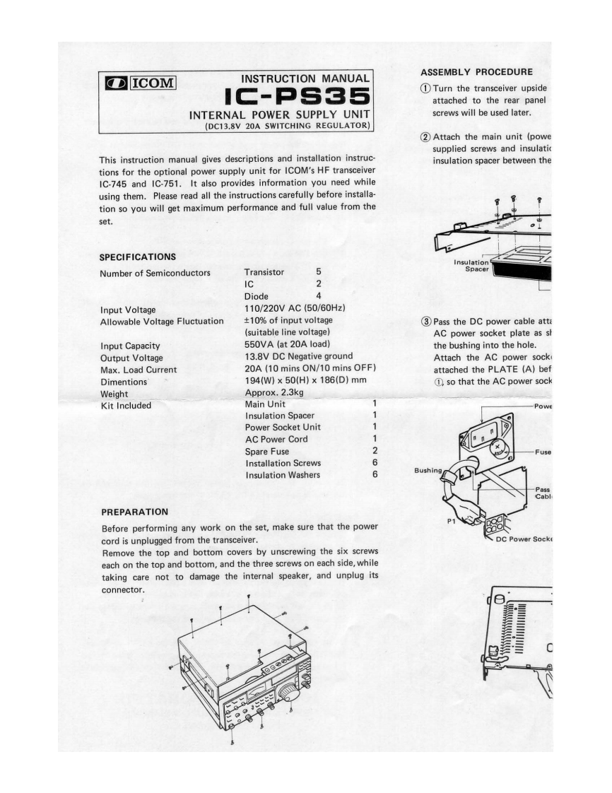
ASSEMBLY PROCEDUREICOMINSTRUCTION MANUALIC-PS351Turn the transceiver upsideattached to the rear panelINTERNAL POWER SUPPLY UNITscrews will be used later.(DC13.8V 20A SWITCHING REGULATOR)2 Attach the main unit (powesupplied screws and insulaticThis instruction manual gives descriptions and installation instruc-insulation spacer between thetions for the optional power supply unit for ICOM's HF transceiverIC-745 and IC-751.It also provides information you need whileusing them.Please read all the instructions carefully before installa-tion so you will get maximum performance and full value from theset.SPECIFICATIONSInsulationNumber of SemiconductorsTransistor5SpacerIC2Diode?Input Voltage110/220VAC(50/60Hz)Allowable Voltage Fluctuation±10%of input voltage3Pass the DC power cable atta(suitable line voltage)AC power socket plate as shInput Capacity550VA (at 20A load)the bushing into the hole.Output Voltage13.8V DC Negative groundAttach the AC power sockMax.Load Current20A(10 mins ON/10 mins OFF)attached the PLATE (A)befDimentions194(W)×50(H)×186(D)mm①,so that the AC power sockWeightApprox.2.3kgKit IncludedMain UnitPowEInsulation Spacer1Power Socket UnitAC Power Cord1Spare Fuse2Us日Installation Screws6Insulation Washers6PassCablPREPARATIONBefore performing any work on the set,make sure that the powercord is unplugged from the transceiver.DC Power SockRemove the top and bottom covers by unscrewing the six screwseach on the top and bottom,and the three screws on each side,whiletaking care not to damage the internal speaker,and unplug itsconnector.

请登录后查看评论内容