
第1页 / 共60页
试读已结束,还剩59页,您可下载完整版后进行离线阅读
THE END
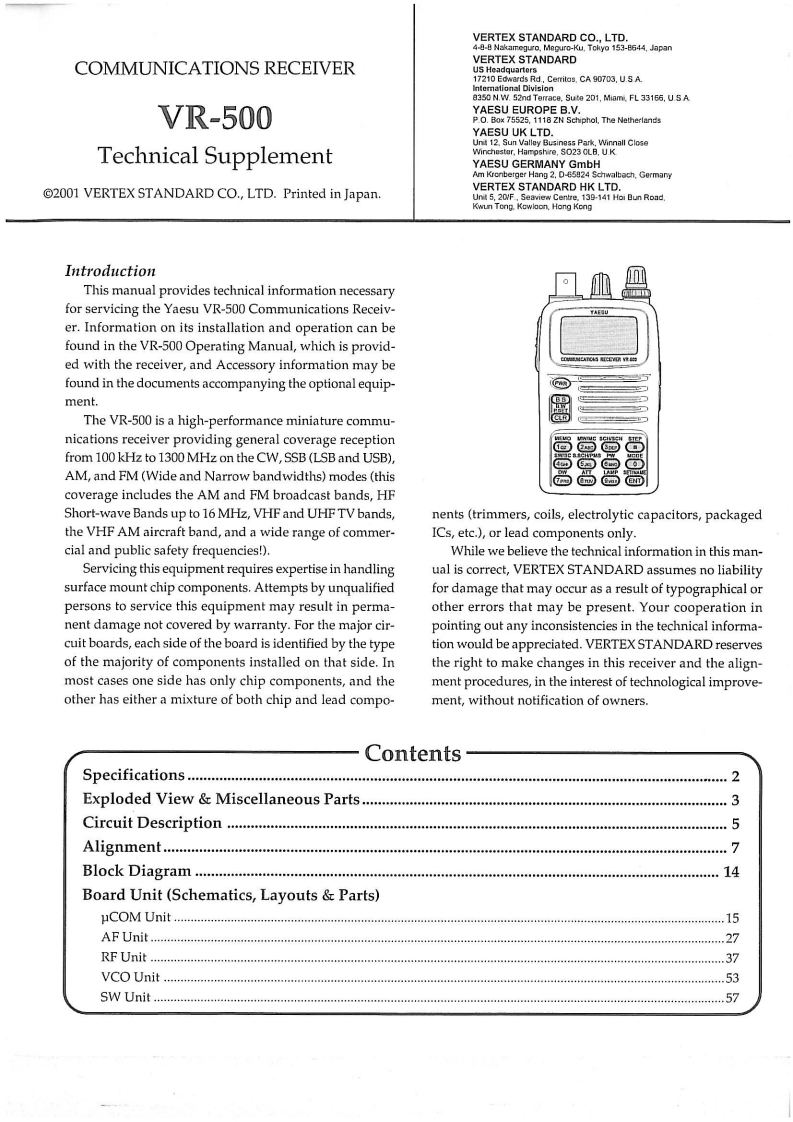
VERTEX STANDARD CO.,LTD.4-8-8 Nakameguro.Meguro-Ku.Tokyo 153-8644.JapanCOMMUNICATIONS RECEIVERVERTEX STANDARDUS Headquarters17210 Edwards Rd,Cerritos,CA 90703,U.S A.w5nc Sute 21,MamVR-500YAESU EUROPE BV.P.O.Box Schphol,The NetherlandsYAESU UK LTD.Unit 12.Sun Valley Businass Park,Winnall CloseTechnical Supplementwinchester.Hampshire,$023 CLB.U.KYAESU GERMANY GmbHAm Kronberger Hang 2.D-65824 Schwalbach.Germany@2001 VERTEX STANDARD CO.,LTD.Printed in Japan.VERTEX STANDARD HK LTD.Unit 5,20/F,Seaview Centre,139-141 Hoi Bun Road,Kwun Tong.Kowloon,Hong KongIntroductionThis manual provides technical information necessaryfor servicing the Yaesu VR-500 Communications Receiv-er.Information on its installation and operation can befound in the VR-500 Operating Manual,which is provid-ed with the receiver,and Accessory information may befound in the documents accompanying the optional equip-ment.The VR-500 is a high-performance miniature commu-nications receiver providing general coverage receptionfrom 100 kHz to 1300 MHz on the CW,SSB (LSB and USB),AM,and FM(Wide and Narrow bandwidths)modes(this高高高coverage includes the AM and FM broadcast bands,HFShort-wave Bands up to 16 MHz,VHF and UHF TV bands,nents (trimmers,coils,electrolytic capacitors,packagedthe VHF AM aircraft band,and a wide range of commer-ICs,etc.),or lead components only.cial and public safety frequencies!).While we believe the technical information in this man-Servicing this equipment requires expertise in handlingual is correct,VERTEX STANDARD assumes no liabilitysurface mount chip components.Attempts by unqualifiedfor damage that may occur as a result of typographical orpersons to service this equipment may result in perma-other errors that may be present.Your cooperation innent damage not covered by warranty.For the major cir-pointing out any inconsistencies in the technical informa-cuit boards,each side of the board is identified by the typetion would be appreciated.VERTEX STANDARD reservesof the majority of components installed on that side.Inthe right to make changes in this receiver and the align-most cases one side has only chip components,and thement procedures,in the interest of technological improve-other has either a mixture of both chip and lead compo-ment,without notification of owners.ContentsSpecifications.........2Exploded View Miscellaneous Parts...3Circuit Description .............66046444644444044444*5Alignment..7Bl0 ck Diagram….14Board Unit (Schematics,Layouts Parts)μCOM Unit15AF Unit…27RFUnit…37VCO Unit.53SW Unit…4.57

请登录后查看评论内容