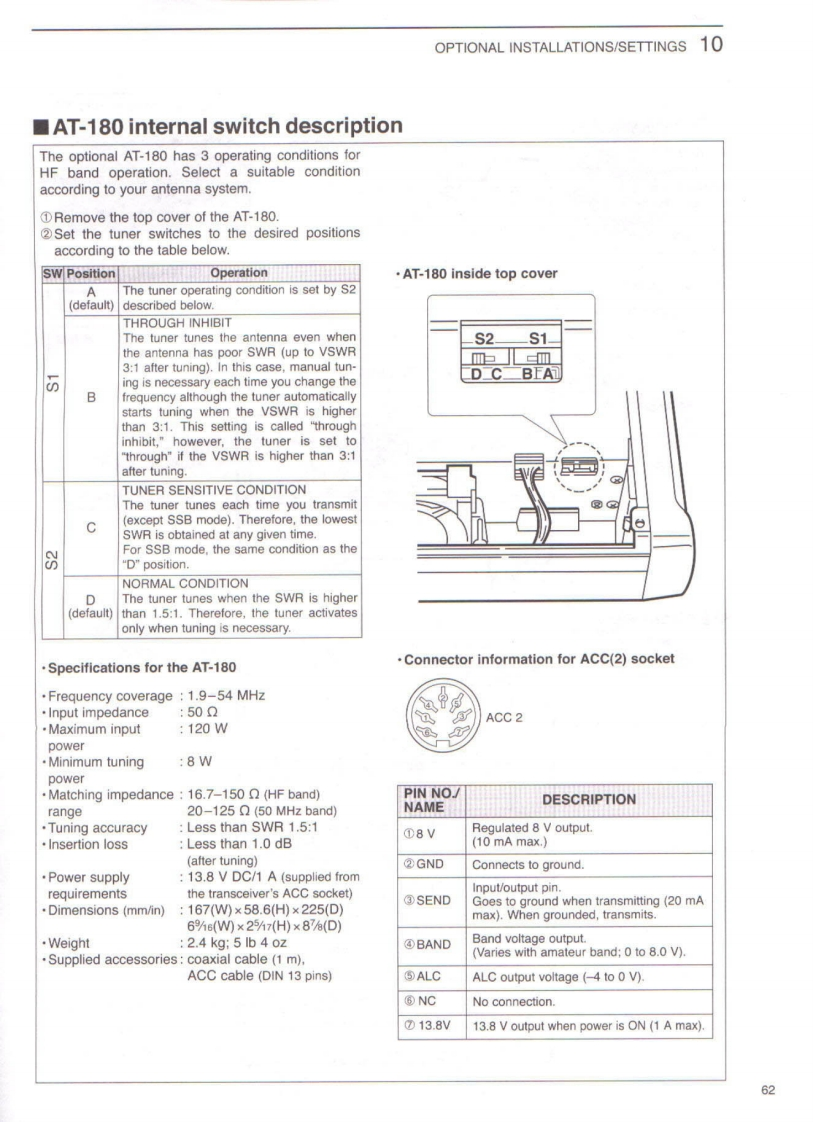
OPTIONAL INSTALLATIONS/SETTINGS10AT-180 internal switch descriptionThe optional AT-180 has 3 operating conditions forHF band operation.Select a suitable conditionaccording to your antenna system.Remove the top cover of the AT-180.2Set the tuner switches to the desired positionsaccording to the table below.SW PositionOperation.AT-180 inside top coverAThe tuner operating condition is set by S2(default)|described below.THROUGH INHIBITThe tuner tunes the antenna even whenS2S1-the antenna has poor SWR(up to VSWRm三m3:1 after tuning).In this case,manual tun-00ing is necessary each time you change theD_C-BEA句Bfrequency although the tuner automaticallystarts tuning when the VSWR is higherthan 3:1.This setting is called "throughinhibit,"however,the tuner is set to"through"if the VSWR is higher than 3:1after tuning.TUNER SENSITIVE CONDITIONThe tuner tunes each time you transmitC(except SSB mode).Therefore,the lowestSWR is obtained at any given time.For SSB mode,the same condition as theD”position.NORMAL CONDITIONDThe tuner tunes when the SWR is higher(default)than 1.5:1.Therefore,the tuner activatesonly when tuning is necessary..Specifications for the AT-180Connector information for ACC(2)socketFrequency coverage 1.9-54 MHzInput impedance:500ACC 2.Maximum input:120WpowerMinimum tuning:8WpowerMatching impedance 16.7-150 (HF band)PIN NO/DESCRIPTIONrange20-125Ω(50 MHz band)NAMETuning accuracyLess than SWR 1.5:1①8VRegulated 8 V output.Insertion lossLess than 1.0 dB(10 mA max.)(after tuning)②GNDConnects to ground.Power supply13.8 V DC/1 A (supplied fromrequirementsthe transceiver's ACC socket)Input/output pin.③SENDDimensions (mm/in)167(W)x58.6(H)x 225(D)Goes to ground when transmitting(20 mAmax).When grounded,transmits.6%6(W0×25%7H)×87%(D).Weight:2.4kg:5b40z④BANDBand voltage output.Supplied accessories:coaxial cable (1 m).(Varies with amateur band;0 to 8.0 V).ACC cable (DIN 13 pins)⑤ALCALC output voltage (-4 to 0 V).®NCNo connection.⑦13.8V13.8 V output when power is ON (1 A max).62

请登录后查看评论内容