
第1页 / 共4页
试读已结束,还剩3页,您可下载完整版后进行离线阅读
THE END
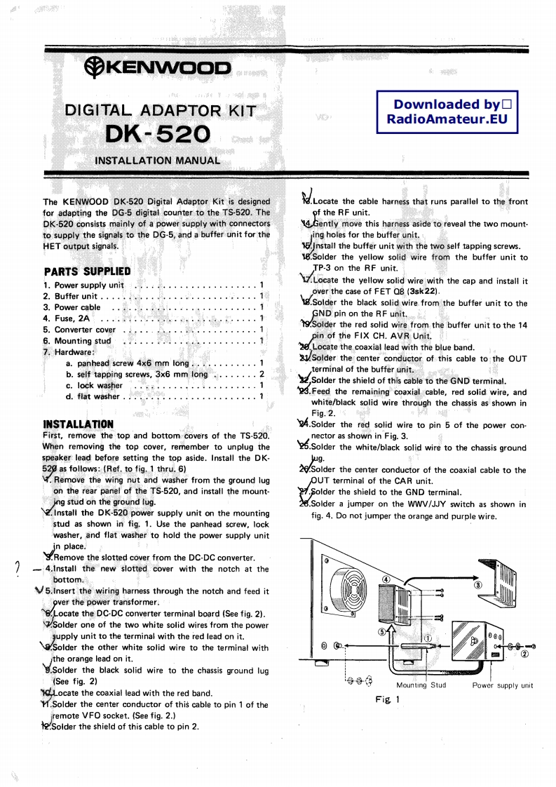
yKENWOODDIGITAL ADAPTOR KITDownloaded by☐RadioAmateur.EUDK-520INSTALLATION MANUALThe KENWOOD DK-520 Digital Adaptor Kit is designedLoctethe cable harness that runs parallel to thefronfor adapting the DG-5 digital counter to the TS-520.Theof the RF unit.DK-520 consists mainly of a power supply with connectors14 Gently move this harness aside to reveal the two mount-to supply the signals to the DG-5,and a buffer unit for theing holes for the buffer unit.HET output signals.15.Install the buffer unit with the two self tapping screws.18.Solder the yellow solid wire from the buffer unit toPARTS SUPPLIEDTP-3 on the RF unit.1.Power supply unitLocate the yellow soid wire with the cap and install it2.Buffer unit.,,,,·,,…1over the case of FET Q8(3sk22)3.Power cableolder the black solid wire from the buffer unit to the4.Fuse,2AGND pin on the RF unit.5.Converter cover9.Solder the red solid wire from the buffer unit to the 14pin of the FIX CH.AVR Unit.6.Mounting stud7.Hardware:2,Locate the coaxial lead with the blue band.a.panhead screw 4x6 mm long............121.Solder the center conductor of this cable to the OUTb.self tapping screws,3x6 mm long........2terminal of the buffer unit.c.lock washer”8f·,····。。。。,1Solder the shield of this cable to the GND terminal.d.flat washer....................3.Feed the remaining coaxial cable,red solid wire,andwhite/black solid wire through the chassis as shown inFig.2.INSTALLATION4.Solder the red solid wire to pin 5 of the power con-First,remove the top and bottom covers of the TS-520.nector as shown in Fig.3.When removing the top cover,remember to unplug the.Solder the white/black solid wire to the chassis groundspeaker lead before setting the top aside.Install the DK-wug.520 as follows:(Ref.to fig.1 thru.6)26.Solder the center conductor of the coaxial cable to theRemove the wing nut and washer from the ground lugOUT terminal of the CAR unit.on the rear panel of the TS-520,and install the mount-Solder the shield to the GND terminal.ing stud on the ground lug.28.Solder a jumper on the WWV/JJY switch as shown in2.Install the DK-520 power supply unit on the mountingfig.4.Do not jumper the orange and purple wire.stud as shown in fig.1.Use the panhead screw,lockwasher,and flat washer to hold the power supply unitin place..Remove the slotted cover from the DC-DC converter.-4.Install the new slotted cover with the notch at thebottom.5.Insert the wiring harness through the notch and feed itover the power transformer.6.Locate the DC-DC converter terminal board (See fig.2).Solder one of the two white solid wires from the powergupply unit to the terminal with the red lead on it..Solder the other white solid wire to the terminal with.the orange lead on it.Solder the black solid wire to the chassis ground lug(See fig.2)导8年Mounting StudPower supply unitLocate the coaxial lead with the red band.M.Solder the center conductor of this cable to pin 1 of theFig 1remote VFO socket.(See fig.2.)Solder the shield of this cable to pin 2.

请登录后查看评论内容