
第1页 / 共5页
试读已结束,还剩4页,您可下载完整版后进行离线阅读
THE END
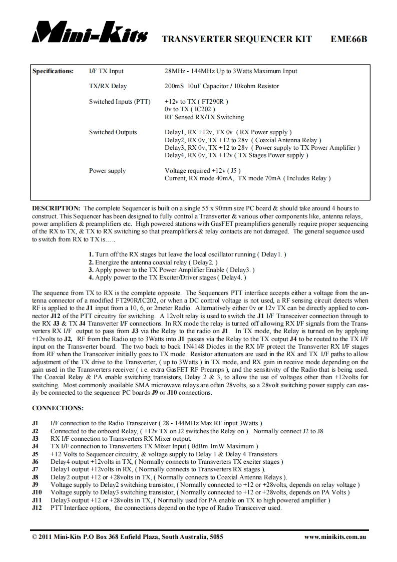
TRANSVERTER SEQUENCER KITEME66BSpecifications:I/F TX Input28MHz-144MHz Up to 3Watts Maximum InputTX/RX Delay200mS 10uF Capacitor/10kohm ResistorSwitched Inputs(PTT)+12v to TX FT290ROv to TX IC202RF Sensed RX/TX SwitchingSwitched OutputsDelayl,RX +12v,TX Ov (RX Power supplyDelay2,RX Ov,TX+12 to 28v Coaxial Antenna RelayDelay3,RX Ov,TX +12 to 28v Power supply to TX Power AmplifierDelay4,RX Ov,TX +12v TX Stages Power supplyPower supplyVoltage required +12v (J5Current,RX mode 40mA,TX mode 70mA Includes RelayDESCRIPTION:The complete Sequencer is built on a single 55 x 90mm size PC board should take around 4 hours toconstruct.This Sequencer has been designed to fully control a Transverter various other components like,antenna relays.power amplifiers preamplifiers etc.High powered stations with GasFET preamplifiers generally require proper sequencingof the RX to TX,TX to RX switching so that preamplifiers relay contacts are not damaged.The general sequence usedto switch from RX to TX is.....1.Turn offthe RX stages but leave the local oscillator running Delay1.2.Energize the antenna coaxial relay Delay2.3.Apply power to the TX Power Amplifier Enable (Delay3.4.Apply power to the TX Exciter/Driver stages Delay4.The sequence from TX to RX is the complete opposite.The Sequencers PTT interface accepts either a voltage from the an-tenna connector of a modified FT290R/IC202,or when a DC control voltage is not used,a RF sensing circuit detects whenRF is applied to the J1 input from a 10,6,or 2meter Radio.Alternatively either Ov or 12v TX can be directly applied to con-nector J12 of the PTT circuitry for switching.A 12volt relay is used to switch the J1 I/F Transceiver connection through tothe RX J3 TX J4 Transverter I/F connections.In RX mode the relay is turned off allowing RX I/F signals from the Trans-verters RX I/F output to pass from J3 via the Relay to the radio on J1.In TX mode,the Relay is turned on by applying+12volts to J2,RF from the Radio up to 3Watts into J1 passes via the Relay to the TX output J4 to be routed to the TX I/Finput on the Transverter board.The two back to back 1N4148 Diodes in the RX I/F protect the Transverter RX I/F stagesfrom RF when the Transceiver initially goes to TX mode.Resistor attenuators are used in the RX and TX I/F paths to allowadjustment of the TX drive to the Transverter,up to 3Watts in TX mode,and RX gain in receive mode depending on thegain used in the Transverters receiver(i.e.extra GasFET RF Preamps )and the sensitivity of the Radio that is being used.The Coaxial Relay PA enable switching transistors,Delay 2 3,to allow the use of voltages other than +12volts forswitching Most commonly available SMA microwave relays are often 28volts,so a 28volt switching power supply can eas-ily be connected to the sequencer PC boards J9 or J10 connections.CONNECTIONS:JII/F connection to the Radio Transceiver(28-144MHz Max RF input 3WattsJ2Connected to the onboard Relay,(+12v TX on J2 switches the Relay on).Normally connect J2 to J

请登录后查看评论内容