
第1页 / 共65页
第2页 / 共65页
试读已结束,还剩63页,您可下载完整版后进行离线阅读
THE END
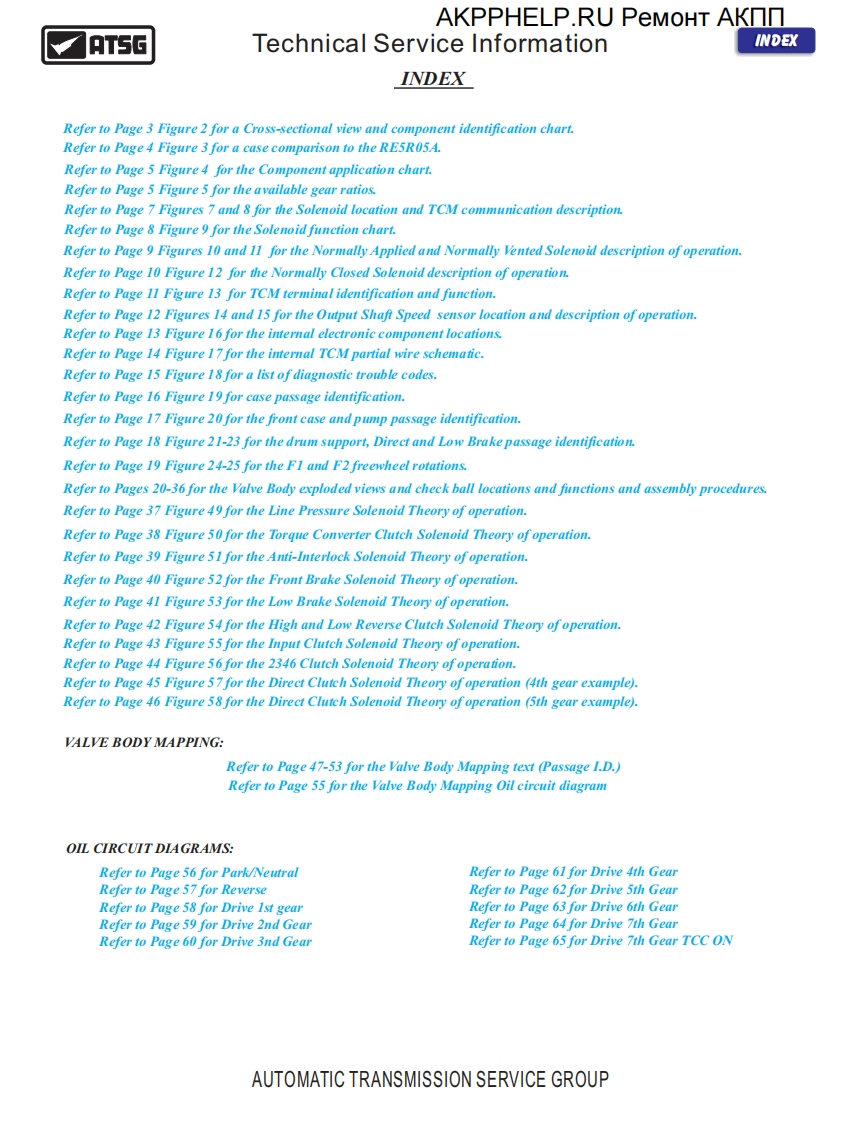
AKPPHELP.RU PeMOHT AKNNATSGTechnical Service InformationINDEXINDEXRefer to Page 3 Figure 2 for a Cross-sectional view and component identification chart.Refer to Page 4 Figure 3 for a case comparison to the RE5R05A.Refer to Page 5 Figure 4 for the Component application chart.Refer to Page 5 Figure 5 for the available gear ratios.Refer to Page 7 Figures 7 and 8 for the Solenoid location and TCM communication description.Refer to Page 8 Figure 9 for the Solenoid function chart.Refer to Page 9 Figures 10 and 11 for the Normally Applied and Normally Vented Solenoid description ofoperation.Refer to Page 10 Figure 12 for the Normally Closed Solenoid description of operation.Refer to Page 11 Figure 13 for TCM terminal identification and function.Refer to Page 12 Figures 14 and 15 for the Output Shaft Speed sensor location and description of operation.Refer to Page 13 Figure 16 for the internal electronic component locations.Refer to Page 14 Figure 17 for the internal TCM partial wire schematic.Refer to Page 15 Figure 18 for a list of diagnostic trouble codes.Refer to Page 16 Figure 19 for case passage identification.Refer to Page 17 Figure 20 for the front case and pump passage identification.Refer to Page 18 Figure 21-23 for the drum support,Direct and Low Brake passage identification.Refer to Page 19 Figure 24-25 for the FI and F2freewheel rotations.Refer to Pages 20-36 for the Valve Body exploded views and check ball locations and functions and assembly procedures.Refer to Page 37 Figure 49 for the Line Pressure Solenoid Theory of operation.Refer to Page 38 Figure 50 for the Torque Converter Clutch Solenoid Theory of operation.Refer to Page 39 Figure 51 for the Anti-Interlock Solenoid Theory of operation.Refer to Page 40 Figure 52 for the Front Brake Solenoid Theory of operation.Refer to Page 41 Figure 53 for the Low Brake Solenoid Theory of operation.Refer to Page 42 Figure 54 for the High and Low Reverse Clutch Solenoid Theory of operation.Refer to Page 43 Figure 55 for the Input Clutch Solenoid Theory of operation.Refer to Page 44 Figure 56for the 2346 Clutch Solenoid Theory of operation.Refer to Page 45 Figure 57 for the Direct Clutch Solenoid Theory of operation (4th gear example).Refer to Page 46 Figure 58 for the Direct Clutch Solenoid Theory of operation (5th gear example).VALVE BODY MAPPING:Refer to Page 47-53 for the Valve Body Mapping text (Passage I.D.)Refer to Page 55 for the Valve Body Mapping Oil circuit diagramOIL CIRCUIT DIAGRAMS:Refer to Page 56 for Park/NeutralRefer to Page 61 for Drive 4th GearRefer to Page 57 for ReverseRefer to Page 62 for Drive 5th GearRefer to Page 58 for Drive 1st gearRefer to Page 63 for Drive 6th GearRefer to Page 59 for Drive 2nd GearRefer to Page 64 for Drive 7th GearRefer to Page 60 for Drive 3nd GearRefer to Page 65 for Drive 7th Gear TCC ONAUTOMATIC TRANSMISSION SERVICE GROUP

请登录后查看评论内容