
第1页 / 共3页
试读已结束,还剩2页,您可下载完整版后进行离线阅读
THE END
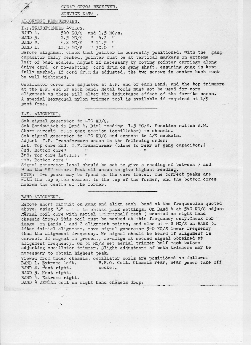
CODAR CR7 OA RECEIVER。SERVICE DATA。ALIGNMENT FREQUENCIES.I.F.TRANSFORMERS 470KCS.BAND 4.540Kc/8and 1.5 MC/s.BAND 3.1.5 MC/s14.21BAND 2.4..2MC/s"11.51BAND 1.11,5MC/S"30.01Before alignment check that pointer is correctay positioned.With thegangcapacitor filly meshed,pointer must be at vertical markers on extremeleft of band scales.Adjust if necessary by moving pointer carriage alongdrive cord,or re-setting cord drum on gang shaft,ensuring gang is keptfully meshed,If cord dr is adjusted;the two screws in centre bush mustbe well tightened。Oscillator cores are adjusted at L.F.end of each Band,and the top trimmersat the H,F。end of each band。Metal too子s must not be used for,corealignment as these will alter the inductance effect of the ferrite cores.A special hexagonal nylon trimmer tool is available if required at 1/9post freeaI,F:ALIGNMENT。Set signal generator to 470 KC/S.Set Bandswitch in Band 4e Dial reading 1.5 MC/S.Function switch A.M.Short circuit gang section (oscillator)to chassis.Set signal generator to 470 KC/S and connect to A/E sockets.Adjust I.F.Transformers cores in the following order:1st.Top core 2nd,IF.Transformer (close to rear of gang capacitor.)2nd。Bottom core"I3rd。Top core1st,I.F。"4th。Bottom core"Signel generator level should be set to give a reading of between 7 and9 on the ist meter.Peak all cores to give highest reading.NOTE:Two peaks may be fpund on the core travel.The correct peaks arewith the top c.res nearest to the top of the former,and the bottom coresneared the centre of the former.BAND ALIGNMENT。Remove short circuit on gang and align each band at the frequencies quotedabove,using "s"to obtain aek settings.On Band 4 at 540 KC/s adjusterial coil core with aerialhalf mesh mounted on right handchassis drop.)This coil.must be peaked at this frequency only.Check forimage on Bands 1 and 2 alignment points,and also at 4.2 MC/s on BAND 3.After initial alignment,move signal generator 940 KC/S lower frequencythan the alignment frequency.No signal should be heard if alignment iscorrect.If signal is present,re-align at second signal obtained atalignment frequency.On 30 MC/s set aerial trimmer half mesh beforeadjusting oscillater trimmer.slight adjustment of both trimmers may benecessary to obtain highest peak.Viewed from undez chassis,oscillator coils are positioned as follows:BAND1。Extreme left。B.F.0.Coil.Chassis rear,near power take offBAND 2.Next right.socket.BAND3。Next right。BAND4。Extreme right,BAND 4AERIAL coil on right hand chassis drop,

请登录后查看评论内容