
第1页 / 共4页
试读已结束,还剩3页,您可下载完整版后进行离线阅读
THE END
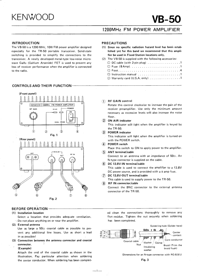
KENWOODVB-501200MHz FM POWER AMPLIFIERINTRODUCTIONPRECAUTIONSThe VB-50 is a 1200 MHz,10W FM power amplifier designed(1)Since no specific radiation hazard level has been estab-especially for the TR-50 portable transceiver.Solid-statelished yet for this band we recommend that this ampli-switching is provided to simplify the connections to thefier be used in Fixed Station locations only.transceiver.A newly developed metal-type low-noise micro-(2)The VB-50 is supplied with the following accessories:wave GaAs (Gallium Arsenide)FET is used to prevent anyDC cable (with 2-pin plug).................1loss of receiver performance when the amplifier is connected□Fuse(8Amp}.,.,........1to the radio.□F0ot.4Instruction manual......................1口Warranty card (U.S.A.only).........··.1CONTROLS AND THEIR FUNCTION(Front panel)①RF GAIN controlKENWOOD 1200MHz FM POWER AMPLIFIERRotate this control clockwise to increase the gain of theRF GAIN-POWERreceiver preamplifier.Use only the minimum amountnecessary as excessive levels will also increase the noisefloor.②ON AIR indicatorThis indicator will light when the amplifier is keyed bythe TR-50.③POWER indicatorFig.1This indicator will light when the amplifier is turned on(Rear panel)with the POWER switch.④POWER switchPlace this switch to ON to apply power to the amplifier.DCr3.8V-ANT⑤ANT terminal/cableConnect to an antenna with an impedance of 50g.AnN-type connector is supplied on the cable.6 DC 13.8V-IN terminal/cableThis cable is used to connect the amplifier to a 13.8VDC power source,and is provided with a 8 amp fuse.7DC 13.8V-OUT terminal/cableThis cable is used to supply power to the TR-50.8 RF IN connector/cableConnect the BNC connector to the external antennaconnector of the TR-50.Fig.2BEFORE·OPERATION(1)Installation locationed clean the connections thoroughly to remove anySelect a location that provides adequate ventilation.flux residue.Tighten the nut securely when soldering--Do not place anything on or near the amplifier.has been completed.(2)External antennaSoldering hole (Solder herelUse as large a 50n coaxial cable as possible to pre-坐!图vent any additional line losses.Use as short a leadCenterin as possible!contact(3)Connection between the antenna connector and coaxialCore conductorCoaxial cableWasher Clampconnector.NutBraid (Trim the(Example)Insulatingwasherbraid flush)Attach the end of the coaxial cable as shown in theillustration.Pay particular attention when solderingDimensions for an N-type connector with RG-8.9/Uthe center conductor.When soldering has been complet-Fig.3

请登录后查看评论内容