
第1页 / 共21页
试读已结束,还剩20页,您可下载完整版后进行离线阅读
THE END
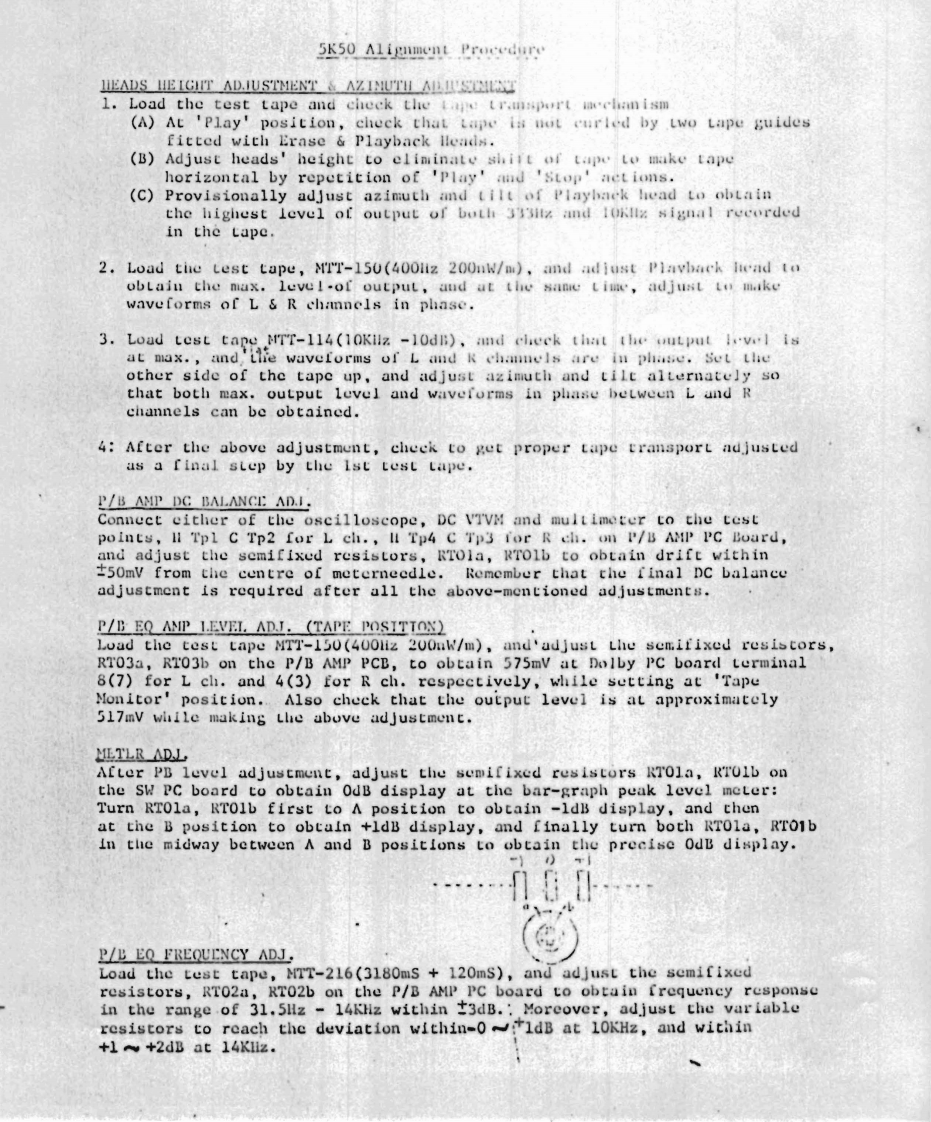
5K50 Alignment ProcedureHEADS HEIGHT AD.IUSTMENT AZINUTH AD IUST1.Load the test tape and check the tr.msport iaehan ism(A)At 'Play'position,check that tape is not curled by two tape guidesfitted with Erase Playback lleads.(B)Adjust heads'height to eliminate shilt of tape to make tapehorizontal by repetition of 'Play'and 'Stop'aet ions.(C)Provisionally adJust azimuth and tilt of Playhack head to obtainthe highest level of output of both 333itz and 10Kllz signal recordedin the Lape.2.Load the test tape,M'IT-150(400liz 200nW/m),and adiust Plavback ltead toobtain the max.leve I-of output,and at the same time,adjust to mkewaveforms of L R channels in phase.3.Load test tape MTT-114(10Kilz -10dl),and cheek that the output lvl isat max.,and,'the waveforms of L and k channels are in phase.Set theother side of the tape up,and adjust azimuth and tilt alternately sothat both max.output level and waveforms in phase between L and Rchannels can be obtained.4:After the above adjustment,check to get proper tape transport adjustedas a final step by the Ist test tape.P/B AMP DC BALANCE AD.I.Connect either of the oscilloscope,DC VTVM and multimeter to the testpoints,ll Tpl C Tp2 for L ch.,ll Tp4 C Tp3 for R ch.on P/B AMP PC Board,and adjust the semifixed resistors,RTola,RTolb to obtain drift within50mV from the centre of meterneedle.Remember that the final DC balanceadjustment is required after all the above-mentioned adjustments.P/D EQ ANP LEVEI.ADJ.(TAPE POSITTON)Load the test tape MTT-150(400liz 200uW/m),and'adjust Lhe semifixed resistors,RT03a,RT03b on the P/B AMP PCB,to obtain 575mV at Dolby PC board terminal8(7)for L ch.and 4(3)for R ch.respectively,while setting at 'TapeMonitor'position..Also check that the output level is at approximately517mV while making the above adJustment.LTLR△DLAfter PB level adjustment,adjust the semifixed resistors RTOla,RT01b onthe SW PC board to obtain OdB display at the bar-graph peak level meter:Turn RTOla,RTOlb first to A position to obtain -1dB display,and thenat the B position to obtain +ldB display,and finally turn both RTOla,RTolbin the midway between A and B positions to obtain the precise OdB display.=】)P/B EQ FREQUENCY ADJ.Load the test tape,MTT-216(3180mS 120mS),and adjust the semifixedresistors,RT02a,RT02b on the P/B AMP PC board to obtain frequency responsein the range of 31.5Hz 14KHz within 3dB.:Moreover,adjust the variableresistors to reach the deviation within-0ldB at 10KHz,and within+l +2dB at 14Kliz.

请登录后查看评论内容