
第1页 / 共24页
试读已结束,还剩23页,您可下载完整版后进行离线阅读
THE END
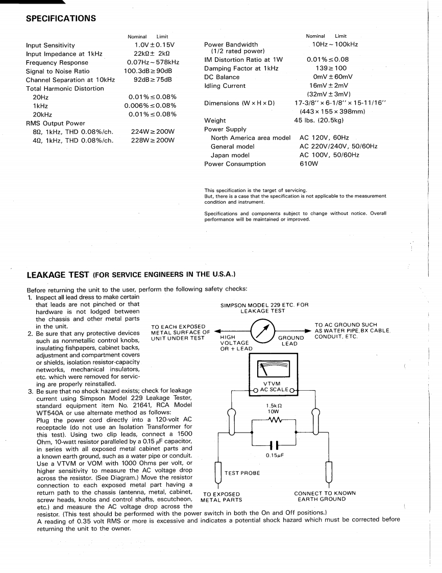
SPECIFICATIONSNominal LimitNominal LimitInput Sensitivity1.0V±0.15VPower Bandwidth10Hz-100kHzInput Impedance at 1kHz22kD±2k0(1/2 rated power)Frequency Response0.07Hz-578kHzIM Distortion Ratio at 1W0.01%≤0.08Signal to Noise Ratio100.3dB≥90dBDamping Factor at 1kHz139≥100Channel Separation at 10kHz92dB≥75dBDC Balance0mV±60mVTotal Harmonic Distortionldling Current16mV±2mV20Hz0.01%≤0.08%(32mV±3mV)1kHz0.006%≤0.08%Dimensions(W×HxD】17-3/8"×6-1/8"×15-11/1620kHz0.01%≤0.08%(443×155×398mm】RMS Output PowerWeight451bs.(20.5kg)82,1kHz,THD0.08%/ch.224W≥200WPower Supply42,1kHz,THD0.08%/ch.228W≥200WNorth America area modelAC 120V,60HzGeneral modelAC220V/240V,50/60HzJapan modelAC100V,50/60HzPower Consumption610WThis specification is the target of servicing.But,there is a case that the specification is not applicable to the measurementcondition and instrument.Specifications and components subject to change without notice.Overallperformance will be maintained or improved.LEAKAGE TEST (FOR SERVICE ENGINEERS IN THE U.S.A.)Before returning the unit to the user,perform the following safety checks:1.Inspect all lead dress to make certainthat leads are not pinched or thatSIMPSON MODEL 229 ETC.FORhardware is not lodged betweenLEAKAGE TESTthe chassis and other metal partsin the unit.TO EACH EXPOSEDTO AC GROUND SUCH2.Be sure that any protective devicesMETAL SURFACE OFAS WATER PIPE BX CABLEHIGHCONDUIT.ETC.such as nonmetallic control knobs,UNIT UNDER TESTGROUNDVOLTAGELEA▣insulating fishpapers,cabinet backs,OR LEADadjustment and compartment coversor shields,isolation resistor-capacitynetworks,mechanical insulators,etc.which were removed for servic-ing are properly reinstalled.VTVM3.Be sure that no shock hazard exists;check for leakageO AC SCALEOcurrent using Simpson Model 229 Leakage Tester,standard equipment item No.21641,RCA Model1.5kWT540A or use alternate method as follows:10WPlug the power cord directly into a 120-volt ACreceptacle (do not use an Isolation Transformer forthis test).Using two clip leads,connect a 1500Ohm,10-watt resistor paralleled by a 0.15 gF capacitor,in series with all exposed metal cabinet parts anda known earth ground,such as a water pipe or conduit.0.15uFUse a VTVM or VOM with 1000 Ohms per volt,orhigher sensitivity to measure the AC voltage dropTEST PROBEacross the resistor.(See Diagram.)Move the resistorconnection to each exposed metal part having areturn path to the chassis (antenna,metal,cabinet,TO EXPOSEDCONNECT TO KNOWNscrew heads,knobs and control shafts,escutcheon,METAL PARTSEARTH GROUNDetc.and measure the Ac voltage drop across theresistor.(This test should be performed with the power switch in both the On and Off positions.)A reading of 0.35 volt RMS or more is excessive and indicates a potential shock hazard which must be corrected beforereturning the unit to the owner.

请登录后查看评论内容