
第1页 / 共54页
试读已结束,还剩53页,您可下载完整版后进行离线阅读
THE END
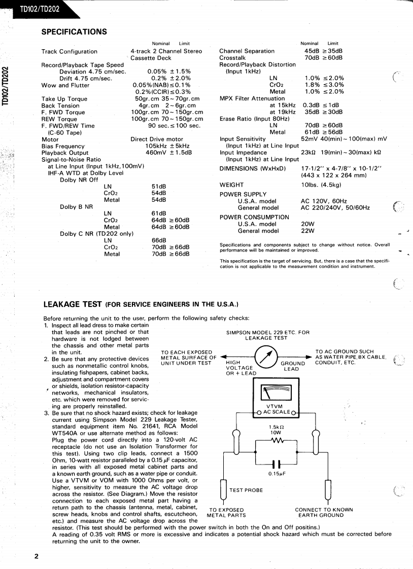
TD102/TD202SPECIFICATIONSNominalLimitNominalLimitTrack Configuration4-track 2 Channel StereoChannel Separation45dB≥35dBCassette DeckCrosstalk70dB≥60dBRecord/Playback Tape SpeedRecord/Playback DistortionDeviation 4.75 cm/sec.0.05%±1.5%(Input 1kHz)Drift 4.75 cm/sec.0.2%±2.0%LN1.0%≤2.0%Wow and Flutter0.05%NAB)≤0.1%CrO21.8%≤3.0%0.2%CC1R)≤0.3%Metal1.0%≤2.0%Take Up Torque50gr.cm 35~70gr.cmMPX Filter AttenuationBack Tension4gr.cm 2-6gr.cmat 15kHz0.3dB≤1dBF.FWD Torque100gr.cm 70-150gr.cmat 19kHz35dB≥30dBREW Torque100gr.cm 70~150gr.cmErase Ratio (Input 80Hz)F.FWD/REW Time90 sec.s 100 sec.LN70dB≥60dB(C-60 Tape)Metal61dB≥56dBMotorDirect Drive motorInput Sensitivity52mV 40(min)-100(max)mVBias Frequency105kHz±5kHz(Input 1kHz)at Line InputPlayback Output460mV±1.5dBInput Impedance23k2 19(min)~30(max)knSignal-to-Noise Ratio(Input 1kHz)at Line Inputat Line Input (Input 1kHz,100mV)DIMENSIONS (WxHxD)17-1/2"×4-7/8"×10-1/2'IHF-A WTD at Dolby Level(443×122×264mm)Dolby NR OffLN51dBWEIGHT10lbs.(4.5kg)CrO254dBPOWER SUPPLYMetal54dBU.S.A.modelAC 120V,60HzDolby B NRGeneral modelAC220/240V,50/60HzLN61dBCrO264dB≥60dBPOWER CONSUMPTIONMetal64dB≥60dBU.S.A.model20WDolby C NR (TD202 only)Generai model22WLN66dBCrO270dB≥66dBSpecifications and components subject to change without notice.Overallperformance will bentained or70dB≥66dBmaimproved.MetalThis specification is the target of servicing.But,there is a case that the specification is not applicable to the measurement condition and instrument.LEAKAGE TEST (FOR SERVICE ENGINEERS IN THE U.S.A.)Before returning the unit to the user,perform the following safety checks:1.Inspect all lead dress to make certainthat leads are not pinched or thatSIMPSON MODEL 229 ETC.FORhardware is not lodged betweenLEAKAGE TESTthe chassis and other metal partsin the unit.TO EACH EXPOSEDTO AC GROUND SUCH2.Be sure that any protective devicesMETAL SURFACE OFAS WATER PIPE.BX CABLE.such as nonmetallic control knobs.UNIT UNDER TESTHIGHGROUNDCONDUIT,ETC.VOLTAGELEADinsulating fishpapers,cabinet backsOR LEADadjustment and compartment coversor shields,isolation resistor-capacitynetworks,mechanical insulatorsetc.which were removed for servic.ing are properly reinstalled.VTVM3.Be sure that no shock hazard exists;check for leakageOAC SCALEOcurrent using Simpson Model 229 Leakage Tester,standard equipment item No.21641,RCA Model1.5knWT540A or use alternate method as follows:10wPlug the power cord directly into a 120-volt ACreceptacle (do not use an Isolation Transformer forthis test).Using two clip leads,connect a 1500Ohm,10-watt resistor paralleled by a 0.15 gF capacitor,in series with all exposed metal cabinet parts anda known earth ground,such as a water pipe or conduit.0.15ufUse a VTVM or VOM with 1000 Ohms per volt,orhigher,sensitivity to measure the Ac voltage dropacross the resistor.(See Diagram.)Move the resistorTEST PROBEconnection to each exposed metal part having areturn path to the chassis (antenna,metal,cabinet,TO EXPOSEDCONNECT TO KNOWNscrew heads,knobs an

请登录后查看评论内容