
第1页 / 共28页
试读已结束,还剩27页,您可下载完整版后进行离线阅读
THE END
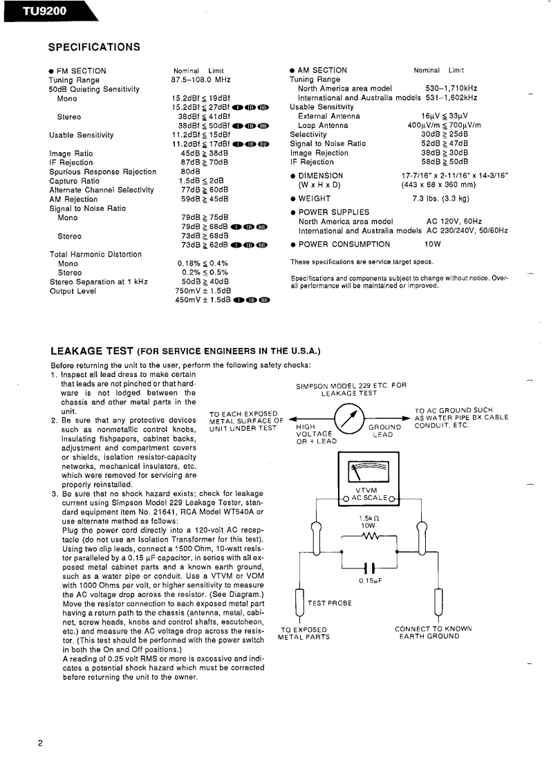
TU9200SPECIFICATIONS·FM SECTIONNominal Limit◆AM SECTIONNominal LimitTuning Range87.5-108.0MHzTuning Range50dB Quieting SensitivityNorth America area model530-1.710kHzMono15.2d8f≤19dBInternational and Australia models 531-1,602kHz15.2dBf≤27dBf日Usable SensitivityStereo38dBf至41dBfExternal Antenna16μVs33μV38dBf≤50dBf血四Loop Antenna400μV/m≤700μV/mUsable Sensitivity11.2dBf s 15dBfSelectivity30dB≥25dB11.2dBf≤17dBf8用Signal to Noise Ratio52dB≥47dBImage Ratio45dB 238dBImage Rejection38dB2 30dBIF Rejection87dB2 70dBIF Rejection58dB 2 50dBSpurious Response Rejection80dB·DIMENSION17-7/16°X2-11/16”×14-3/16Capture Ratio1.5dB s 2dB(443X68X360mm}Alternate Channel Selectivity77dB≥60dB(W x H x D)AM Rejection59dB 45dBWEIGHT7.31b8.3.3kg)Signal to Noise Ratio●POWER SUPPLIESMono79dB 2 75dBNorth America area modolAC 120V,60Hz79dB268dB①BBInternational and Australia models AC 230/240V,50/60HzStereo73dB >68dB73dB≥62dBmR●POWER CONSUMPTION10WTotal Harmonic DistortionMono0.18%三0.4%These specifications are service target specs.Stcroo0.2%≤0.5%Stereo Separation at 1 kHz50dB z 40dBSpecifications and components subject to change without notice.Over-all performance witl be maintained or improved.Output Level750mV±1.5dB450mV±1.5d8B6邵LEAKAGE TEST (FOR SERVICE ENGINEERS IN THE U.S.A.)Before returning the unit to the user,perform the following safety checks:1.Inspect all lead dress to make certainthat leads are not pinched or that hard-SIMPSON MODEL 229 ETC.FORware is not lodged between theLEAKAGE TESTchassis and other metal parts in theunit.TO EACH EXPOSEDTO AC GROUND SUCH2.Be sure that any protective devicesMETAL SURFACE OFAS WATER PIPE BX CABLEsuch as nonmetallic control knobs,UNIT UNDER TESTHIGHGROUNDCONDUIT.ETC.VOLTAGEinsulating fishpapers,cabinet backs,OR LEADadjustment and compartment coversor shields,isolation resistor-capacitynetworks,mechanical insulators,etc.which were removed for servicing areproperly reinstalled.3.Be sure that no shock hazard exists;check for leakageVTVMcurrent using Simpson Model 229 Leakage Tester,stan-O AC SCALEOdard equipment item No.21641,RCA Model WT540A oruse alternate method as follows:1.5kPlug the power cord directly into a 120-volt AC recep-10Wtacle (do not use an Isolation Transformer for this test).Using two clip leads,connect a 1500 Ohm,10-watt resis-tor paralleled by a 0.15 uF capacitor.in series with all ex-posed metal cabinet parts and a known earth groundsuch as a water pipe or conduit.Use a VTVM or VOM0.15Fwith 1000 Ohms per volt,or higher sensitivity to measurethe AC voltage drop across the resistor.(See Diagram.)Move the resistor connection to each exposed metal partTEST PROBEhaving a return path to the chassis (antenna,metal,cabi-net,screw heads,knobs and control shafts,escutcheonetc.)and measure the AC voltage drop across the resis-TO EXPOSEDCONNECT TO KNOWNtor.(This test should be performed with the power switchMETAL PARTSEARTH GROUNDin both the On and Off positions.A reading of 0.35 volt RMS or more is excessive and indi-cates a pote

请登录后查看评论内容