
第1页 / 共12页
试读已结束,还剩11页,您可下载完整版后进行离线阅读
THE END
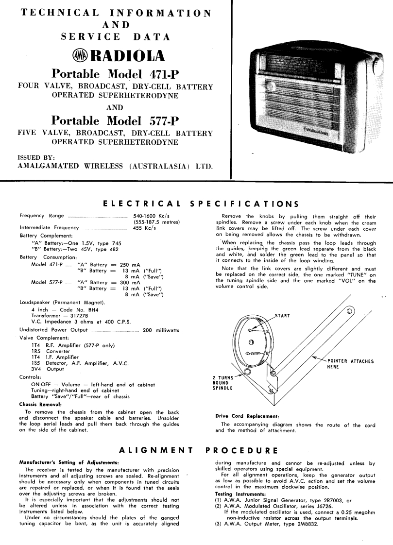
TECHNICAL INFORMATIONANDSERVICE DATA©RADIOLAPortable Model 471-PFOUR VALVE,BROADCAST,DRY-CELL BATTERYOPERATED SUPERHETERODYNEANDPortable Model 577-PFIVE VALVE,BROADCAST,DRY-CELL BATTERYOPERATED SUPERHETERODYNEISSUED BY:AMALGAMATED WIRELESS (AUSTRALASIA)LTD.ELECTRICAL SPECIFICATIONSFrequency Range...540-1600Kc/5(555-187.5 metres)Remove the knobs by pulling them straight off theirspindles.Remove a screw under each knob when the creamIntermediate Frequency455 Kc/slink covers may be lifted off.The screw under each coverBattery Complement:on being removed allows the chassis to be withdrawn."A"Battery:-One 1.5V,type 745When replacing the chassis pass the loop leads through"B"Battery:-Two 45V,type 482the guides,keeping the green lead separate from the blackBattery Consumption:and white,and solder the green lead to the panel so thatModel471-P一"A”Battery=250mAit connects to the inside of the loop winding."B"Battery 13 mA ("Full")Note that the link covers are slightly different and must8 mA ("Save")be replaced on the correct side,the one marked "TUNE"onModel 577-P"A"Battery =300 mAthe tuning spindle side and the one marked "VOL"on the"B"Battery 13 mA ("Full")volume control side,8 mA ("Save")Loudspeaker (Permanent Magnet).4 inch Code No.BH4Transformer -31727BSTARTV.C.Impedance 3 ohms at 400 C.P.S.Undistorted Power Output ....200 milliwattsValve Complement:1T4 R.F.Amplifier (577-P only)1R5Converter1T4 I.F.Amplifier1S5 Detector,A.F.Amplifier,A.V.C.POINTER ATTACHES3V4 OutputHEREControls:2 TURNSON-OFF-Volume -left-hand end of cabinetROUNDTuning-right-hand end of cabinetSPINDLEBattery "Save"/"Full"-rear of chassisChassis Removal:To remove the chassis from the cabinet open the backand disconnect the speaker cable and batteries.UnsolderDrive Cord Replacement:the loop aerial leads and pull them back through the guidesThe accompanying diagram shows the route of the cordon the side of the cabinet.and the method of attachment.ALIGNMENTPROCEDUREManufacturer's Setting of Adjustments:during manufacture and cannot be re-adjusted unless byThe receiver is tested by the manufacturer with precisionskilled operators using special equipment.instruments and all adjusting screws are sealed.Re-alignmentFor all alignment operations,keep the generator outputshould be necessary only when components in tuned circuitsas low as possible to avoid A.V.C.action and set the volumeare repaired or replaced,or when it is found that the sealscontrol in the maximum clockwise position.over the adjusting screws are broken.Testing Instruments:It is especially important that the adjustments should not(1)A.W.A.Junior Signal Generator,type 2R7003,orbe altered unless in association with the correct testing(2)A.W.A.Modulated Oscillator,series J6726.instruments listed below.If the modulated oscillator is used,connect a 0.25 megohmUnder no circumstances should the plates of the gangednon-inductive resistor across the output terminals.tuning capacitor be bent,as the unit is accurately aligned(3)A.W.A.Outpu

请登录后查看评论内容