
第1页 / 共4页
试读已结束,还剩3页,您可下载完整版后进行离线阅读
THE END
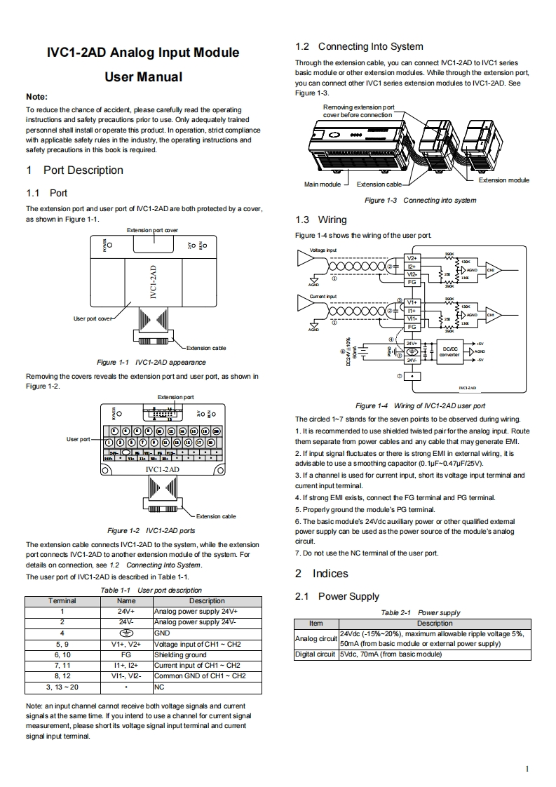
IVC1-2AD Analog Input Module1.2 Connecting Into SystemThrough the extension cable,you can connect NVC1-2AD to IVC1 seriesUser Manualbasic module or other extension modules.While through the extension port,you can connect other IVC1 series extension modules to IVC1-2AD.SeeNote:Figure 1-3.To reduce the chance of accident,please carefully read the operatingRemoving extension portcover before connectioninstructions and safety precautions prior to use.Only adequately trainedpersonnel shall install oroperate this product.In operation,strict compliancewith applicable safety rules in the industry,the operating instructions andsafety precautions in this book is required.1 Port DescriptionMain moduleExtension cableExtension module1.1 PortFigure 1-3 Connecting into systemThe extension port and user port of /C1-2AD are both protected by a cover,as shown in Figure 1-1.1.3 WiringExdension port coverFigure 1-4 shows the wiring of the user porto00V240000000@+241+0000000@-91+User por coverV1-W■0-Exension cable24士Figure 1-1 IVC1-2AD appearanceRemoving the covers reveals the extension port and user port,as shown inFigure 1-2.Edension portFigure 1-4 Wiring of IVC1-2AD user porto世0蓝0The circled 1-7 stands for the seven points to be observed during wiring.回回回回回回回回回回1.It is recommended to use shielded twis led pair for the analog input.RouteUser part-可回回回回回回回回回them separate from power cables and any cable that may generate EMI.中中中中2.If input signal fluctuates or there is strong EMI in external wiring,it isadvis able to use a smoothing capacitor (0.1uF-0.47uF/25V).IVCI-2AD3.If a channel is used for current input,short its voltage input terminal andcurrent input terminal.4.If strong EMI exists,connect the FG terminal and PG terminal.-■5.Properly ground the module's PG terminal.-Edension cable6.The basic module's 24Vdc auxiliary power or other qualified exlemalFigure 1-2 /VC1-2AD portspower supply can be used as the power source of the module's analogThe extension cable connects IVC1-2AD to the system,while the extensioncircuit.port connects IVC1-2AD to another extension module of the system.For7.Do not use the NC terminal of the user portdetails on connection,see 1.2 Connecting Into System.The user port of IVC1-2AD is described in Table 1-1.2 IndicesTable 1-1 User port descriptionTerminalNameDescription2.1 Power Supply124V+Analog power supply 24V+Table 2-1 Power supply224VAnalog power supply 24VItemDescriptionGND24Vdc (-15%~20%),maximum allowable ripple voltage 5%,Analog circuit5,9V1+,V2+Voltage input of CH1 CH250mA(from basic module or external power supply)6.10FGShielding groundDigital circuit 5Vdc,70mA (from basic module)7,1111+,124Current input of CH1~CH28,12V11-,V2-Common GND of CH1-CH23,13-20NCNote:an input channel cannot receive both voltage signals and currentsignals at the same time.If you intend to use a channel for current signalmeasurement,please short its voltage signal input terminal and currentsignal input terminal.

请登录后查看评论内容