
第1页 / 共4页
试读已结束,还剩3页,您可下载完整版后进行离线阅读
THE END
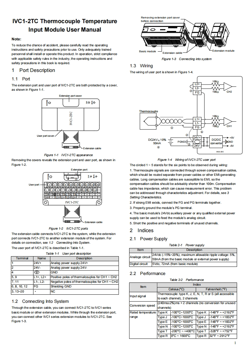
Removing extension port coverIVC1-2TC Thermocouple Temperaturebefare conneefonInput Module User Manual○tNote:To reduce the chance of accident,please carefully read the operatinginstructions and safety precautions prior to use.Only adequately trainedBasic modulexension modulepersonnel shall install or operate this product.In operation,strict complianceExtension cablewith applicable safety rules in the industry,the operating instructions andFigure 1-3 Connecting into systemsafety precautions in this book is required.1.3 Wiring1 Port DescriptionThe wiring of user port is shown in Figure 1-4.1.1 PortThe extension port and user port of NVC1-2TC are both protected by a cover,as shown in Figure 1-1.0且0ThermocoupleL1+L1-FGCH1User port cover24V++5/DC24V±10%PGNDDC/DCGND50mA0neΠe.5Extension cableIC-reFigure 1-1 /VC1-2TC appearanceRemoving the covers reveals the extension port and user port,as shown inFigure 1-4 Wiring of /VC1-2TC user portFigure 1-2.The circled 1~5 stands for the six points to be observed during wiring:Extension port1.Thermocouple signals are connecled through screen compensation cableso0蓝0which should be routed separate from power cables or other EMI-generatingcables.Long compensation cables are susceptible to EMI,so theUserportcompensation cables should be advisably shorter than 100m.CompensationOo⑥回回回国国回国cable has impedance,which can cause measurement error.This problem中中中中can be addressed through characteristics adjustment.For details,see 3Setting Characteristics.IVCI-2TC2.If strong EMI exists,connect the FG and PG terminals together3.Properly ground the module's PG terminal.4.The bas ic module's 24Vdc auxiliary power or any qualified external powersupply can be used to feed the module's analog circuit.Edension cable5.Short the positive and negative terminals of unused channels.Figure 1-2 IVC1-2TC ports2 IndicesThe extension cable connects IVC1-2TC to the system,while the extensionport connects IVC1-2TC to another exlension module of the system.For2.1 Power Supplydetails on connection,see 1.2 Connecting Into System.Table 2-1 Power supplyThe user port of IVC1-2TC is described in Table 1-1.ItemDescriptionTable 1-1 User port description24Vdc (-15%~20%),maximum allowable ripple voltage:5%.NameDescriptionAnaloge circuit50mA (from the basic module or extemal power supply)24V+Analog power supply 24V+Digital circuit5Vdc,72mA (from basic module)24W.Analog power supply 24V.GND2.2Performance5,9L1+,L2+Positive poles of thermalcouples for CH1~CH27,11L1-,L2Table 2-2 PerfommanceNegative poles of thermalcouples for CH1 -CH26,8,10,12IndexFGShielding GNDltemCelsius(C)Fahrenheit(F)3,13-20NCThermocouple:type K,J,E,N,T,R or S (all accessiblenput signalto each channel).2 channels1.2Connecting Into System(240ms+2%)ms x 2 channels (no conversion for unusedThrough the exlension cable,you can connect NC1-2TC to IVC1 seriesCorversion speedchannels)bas ic module or other extension modules.While through the extension port,Rated temperatureType K-100*C-1200*C Type K

请登录后查看评论内容