
第1页 / 共4页
试读已结束,还剩3页,您可下载完整版后进行离线阅读
THE END
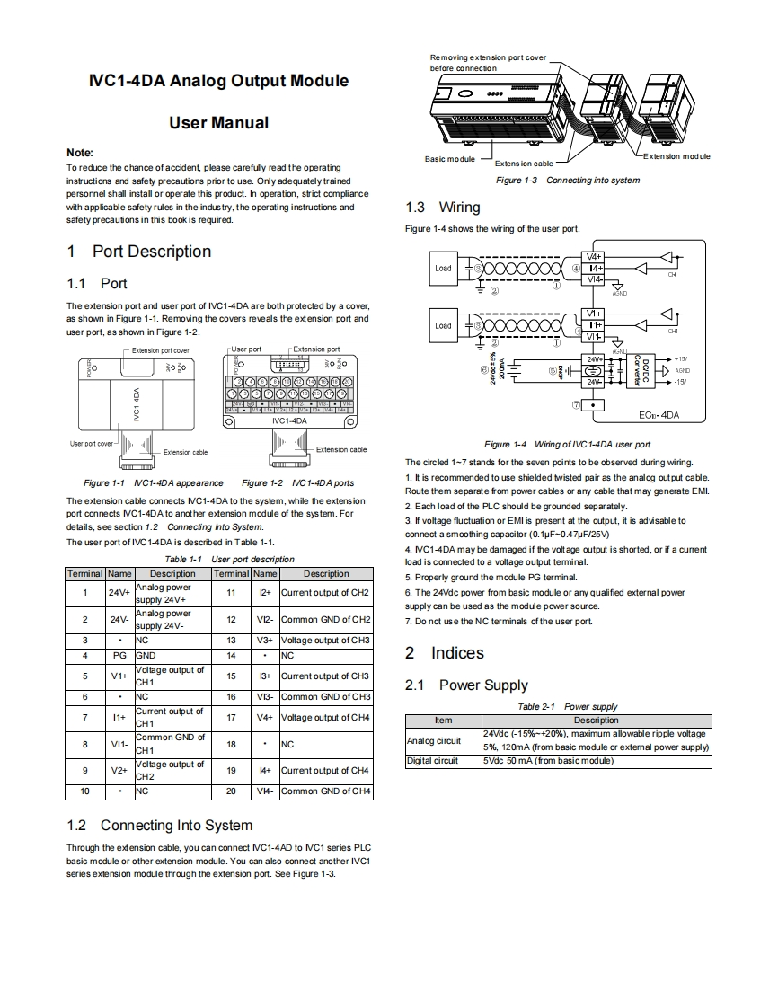
Re moving exten sion port coverbefore connectonIVC1-4DA Analog Output ModuleUser ManualNote:Basic moduleExtension moduleTo reduce the chance of accident,please carefully read the operatingExtension cableinstructions and safety precautions prior to use.Only adequately trainedFigure 1-3 Connecting into systempersonnel shall install or operate this product.In operation,strict compliancewith applicable safety rules in the indus try,the operating instructions and1.3 Wiringsafety precautions in this book is required.Figure 1-4 shows the wiring of the user port1 Port Description4+Load④4+1.1 PortV4-The extension port and user port of IVC1-4DA are both protecled by a cover,as shown in Figure 1-1.Removing the covers reveals the extension port and1+user port,as shown in Figure 1-2+000000011+V+Exension port coverUser portExtension port050西丁o30品出品品出盟中ECD-4DAIVC1-4DAoExtension cableFigure 1-4 Wiring of /VC 1-4DA user port回The circled 1-7 stands for the seven points to be observed during wiring.Figure 1-1 IVC1-4DA appearanceFigure 1-2 IVC 1-4DA ports1.It is recommended to use shielded twisted pair as the analog output cable.Route them separate from power cables or any cable that may generate EMI.The extension cable connects IVC1-4DA to the syslem,while the extension2.Each load of the PLC should be grounded separatelyport connects IVC1-4DA to another extension module of the system.Fordetails,see section 1.2 Connecting Into System.3.If voltage fluctuation or EMI is present at the output,it is advisable toconnect a smoothing capacitor (0.1uF-0.47uF/25V)The user port of IVC1-4DA is described in Table 1-1.4.IC1-4DA may be damaged if the volt age output is shorted,or if a currentTable 1-1 User port descriptionload is connected to a voltage output terminal.DescriptionTerminalNameDescription5.Properly ground the module PG terminal.124V4Analog power2+Current output of CH2supply 24V+176.The 24Vdc power from basic module or any qualified external powersupply can be used as the module power source.224VAnalog power12VI2-Common GND of CH2supply 24V-7.Do not use the NC terminals of the user port3NC13V3+Voltage output of CH34PGGND14NC2IndicesV1+Voltage output of153+Current output of CH3CH12.1Power Supply6NC16V3-Common GND of CH3Current output ofTable 2-1 Power supply711+17V4+Voltage output of CH4CH1ItemDescriptionCommon GND of24Vdc (-15%~+20%),maximum allowable ripple voltageV11-18NCAnalog circuitCH15%,120mA(from basic module or extemal power supply)Digital circuit5Vdc 50 mA (from basic module)9V2+Volt怕ge output ofCH2194+Current output of CH410NC20V4-Common GND of CH41.2 Connecting Into SystemThrough the extension cable,you can connect NC1-4AD to NC1 series PLCbasic module or other extension module.You can also connect another IVC1series exlension module through the extension port.See Figure 1-3.

请登录后查看评论内容