
第1页 / 共4页
试读已结束,还剩3页,您可下载完整版后进行离线阅读
THE END
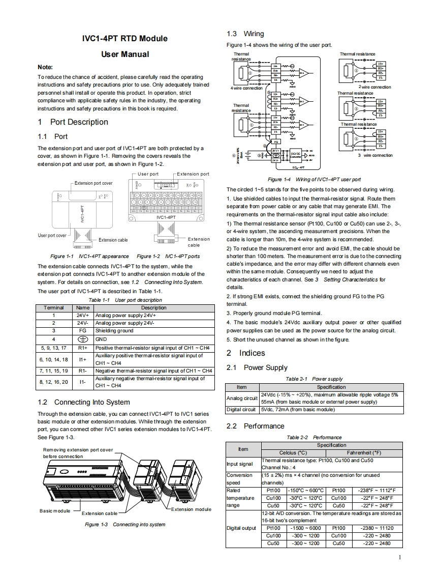
IVC1-4PT RTD Module1.3 WiringFigure 1-4 shows the wiring of the user port.User Manualhermal resiancNote:To reduce the chance of accident,please carefully read the operatinginstructions and safety precautions prior to use.Only adequately trainedpersonnel shall install or operate this product.In operation,strictThemmal tesistancecompliance with applicable safety rules in the industry,the operatinginstructions and safety precautions in this book is required.1 Port DescriptionThemal res is tance1.1 PortThe extension port and user port of IVC1-4PT are both protected by acover,as shown in Figure 1-1.Removing the covers reveals theec0mef0extension port and user port,as shown in Figure 1-2.EC-4PT-User portExtension portFigure 1-4 Wring of /VC1-4PT user portExtension port ooverooThe circled 1-5 stands for the five points to be observed during wiring.'ooOo@@@网©o⊙o⊙⊙⊙©@©©⊙1.Use shielded cables to input the thermal-resistor signal.Route themseparate from power cable or any cable that may generate EMI.TheIVC1-4PTrequirements on the thermal-resistor sig nal input cable also include:1)The themmal resistance sensor (Pt100,Cu100 or Cu50)can use 2-,3-,or 4-wire system,the ascending measurement precisions.When theUser port cover-Extension cable-■10Extensioncable is longer than 10m,the 4-wire system is recommended.cable2)To reduce the measurement error and avoid EMI,the cable should beFigure 1-1IVC1-4PT appearanceFigure 1-2 /VC1-4PTportsshorter than 100 meters.The measurement error is due to the connectingThe extension cable connects IVC1-4PT to the system,while thecable's impedance,and the error may differ with different channels evenextension port connects IVC1-4PT to another extension module of thewithin the same module.Consequently we need to adjust thesystem.For details on connection,see 1.2 Connecting Into System.characteristics of each channel.See 3 Setting Characteristics forThe user port of IVC1-4PT is described in Table 1-1.details.Table 1-1 User port description2.If strong EMI exists,connect the shielding ground FG to the PGTerminalNameDescriptionterminal.124V+Analog power supply 24V+3.Properly ground modulePG temminal.224Analog power supply 24V-4.The basic module's 24Vdc auxiliary output power or other qualified3FGShielding groundpower supplies can be used as the power source for the analog circuit.49GND5.Short the unused channel as shown in the figure.5,9,13,17R1+Positive thermal-resistor signal input of CH1 ~CH4Auxiliary positive thermal-res istor signal input of2Indices6.10.14,181+CH1-CH47,11,15,19R1-Negative thermal-resistor signal input of CH1~CH42.1 Power Supply8.12.16,2011Auxiliary negative thermal-resistor signal input ofTable 2-1 Power supplyCH1-CH4ItemSpecificationAnalog circuit24Vdc (-15%-+20%),maximum allowable ripple voltage 5%12Connecting Into System55mA (from basic module or external power supply)Digital circuit 5Vdc.72mA (from basic module)Through the extension cable,you can connect IVC1-4PT to IVC1 seriesbasic module or other extension m

请登录后查看评论内容