
第1页 / 共4页
试读已结束,还剩3页,您可下载完整版后进行离线阅读
THE END
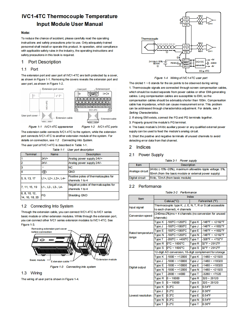
IVC1-4TC Thermocouple TemperatureInput Module User Manual盘一父Note:To reduce the chance of accident,please carefully read the operatingThermocouplinstructions and safety precautions prior to use.Only adequately trainedpersonnel shall install or operate this product.In operation,strict compliance1+L1with applicable safety rules in the industry,the operating instructions andFGsafety precautions in this book is required.1 Port Description24V24货A0%三DC/DC1.1 PortECp 4TCThe extension port and user port of IVC1-4TC are both protected by a coveras shown in Figure 1-1.Removing the covers reveals the extension port andFigure 1-4 Wiring of /VC 1-4TC user portuser port,as shown in Figure 1-2.The circled 1 ~6 stands for the six points to be observed during wiring:-Extension port cover-Ectensionport1.Thermocouple signals are connected through screen compensation cables,中0owhich should be routed separate from power cables or other EMI-generatingo5ocables.Long compensation cables are susceptible to EMI,so thecompensation cables should be advisably shorter than 100m.Compensationcable has impedance,which can cause measurement error.This problemNVC1-4TCδcan be addressed through characteristics adjustment.For details,see 3Setting Characteristics.User port coverExtension cable2.If strong EMI exists,connect the FG and PG terminals logether3.Properly ground the module's PG terminal.Figure 1-1 /VC1-4TC appearanceFigure 1-2 IVC1-4TC ports4.The basic module's 24Vdc auxiliary power or any qualified external powerThe extension cable connects IC1-4TC to the system,while the extensionsupply can be used to feed the module's analog circuit.port connects IVC1-4TC to another extension module of the system.For5.Short the positive and negative terminals of unused channels to avoiddetails on connection,see 1.2 Connecting Into System.detecting error data from that channel.The user port of IVC1-4TC is described in Table 1-1.2 IndicesTable 1-1 User port descriptionTerminalNameDescription2.1 Power Supply24V4Analog power supply 24V+Table 2-1 Power supply224VAnalog power supply 24V-ItemDescription3NC24Vdc (-15%-20%),maximum alloweble ripple voltage:5%,DGNDAnaloge circuit50mA (from the bas ic module or extemal power supply)5,9,13.17Positive poles of thermalcouples forL1+,L2+,L3+,L4+Digital circuit5Vdc,72mA (from basic module)channels 1 to 4Negative poles of thermalcouples for7,11,15,19L1-,L2-,L3-,L4-22Perfommancechannels 1 to 46.8,10.12.Table 2-2 Performance14,16.18.20FGShielding GNDIndexItemCelsius(C)Fahrenheit (F)12Connecting Into SystemThermocouple:type K,J.E,N,T.R or S(all accessiblenput signalto each channel),4 channelsThrough the extension cable,you can connect IC1-4TC to IVC1 series(240ms+2%)ms x 4 channels (no conversion for unusedbasic module or other extension modules.While through the extension port,Conversion speedchannels)you can connect other NC1 series extension modules to IVC1-4TC.SeeType K-100C-1200CType K-148F-+2192℉Figure 1-3.Type J,100'C-1000'CType J-148℉-+1832℉Removing e

请登录后查看评论内容