
第1页 / 共4页
试读已结束,还剩3页,您可下载完整版后进行离线阅读
THE END
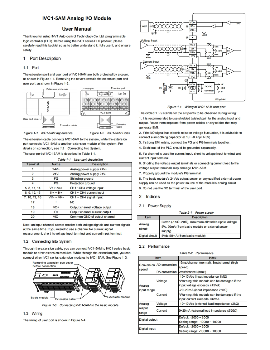
IVC1-5AM Analog l/O ModuleVO+000d0+User Manual0-Thank you for using INVT Auto-control Technology Co.Ltd.programmablelogic controller (PLC).Before using the IVC1 series PLC product,pleaseVoltage inputcarefully read this booklet so as to better understand it,fully use it,and ensureV4+safety.14+VH.FG1 Port DescriptionCurrent input141.1 PortThe extension port and user port of IVC1-5AM are both protected by a cover,1-FGas shown in Figure 1-1.Removing the covers reveals the extension port anduser port,as shown in Figure 1-2.Extension port cover-User port-Exension port00p于05o@⊙⊙⊙@@回③@回EC5AM0⊙⊙①o①©⑩@⑩Figure 1-4 Wiring of /VC1-5AM user portIVC1-5AMOThe circled 1-9 stands for the six points to be observed during wiring:User port cove1.It is recommended to use shielded twis ted pair for the analog input andoutput.Route them separate from power cables or amy cables that mayExtension cableCablegenerate EMI.Figure 1-1 IVC1-5AM appearanceFigure 1-2 IVC1-5AM Ports2.If the 1/O signal has electric noise or voltage fluctuation,it is advisable toconnect a smoothing capacitor (0.1uF-0.47uF/25V).The extension cable connects IC1-5AM to the system,while the extens ionport connects IVC1-5AM to another extension module of the sys tem.For3.If strong EMI exists,connect the FG and PG terminals together.details on connection,see 1.2 Connecting Into System.4.Each load of the PLC should be grounded separately.The user port of IVC1-5AMis described in Table 1-1.5.If a channel is used for current input,short its voltage input terminal andTable 1-1 User port descriptioncurrent input terminal.TerminalNameDescription6.Shorting the voltage output temminals or connecting current load to the124V+Analog power supply 24V+voltage output terminals may damage NC1-5AM.224VAnalog power supply 24V-7.Properly ground the module's PG terminal.FGShileding ground8.The basic module's 24Vdc output power or any qualified extemal power4PGProtection groundsupply can be used as the power source of the module's analog circuit.5.8.11,14V1+-V4+CH1-CH4 voltage input9.Do not use the NC terminal of the user port.6,9,12,1511+-4+CH1-CH4 current input7,10.13,16VI1--V4-CH1 CH4 signal input2Indices17NC18VO+Output channel voltage output2.1 Power Supply1910+Output channel current outputTable 2-1 Power supply20VIO-Common GND of output channelItemDescription24Vdc (-15%~20%),maximum allowable ripple voltageNote:an input channel cannot receive both voltage signals and current signalsAnalog5%,90mA (from basic module or external powerat the same time.If you intend to use a channel for current signalcircuitsupply)measurement,short its volt age input terminal and current input terminal.Digital circuit5Vdc 50mA (from basic module)1.2 Connecting Into SystemThrough the extension cable,you can connect NC1-5AM to IVC1 series basic2.2 Performancemodule or other extension modules.While through the extension port,you canTable 2-2 Performanceconnect other IVC1 series exlension modules to IVC1-5AM.See Figure 1-3.ItemIndexRemoving exten

请登录后查看评论内容