
第1页 / 共7页
试读已结束,还剩6页,您可下载完整版后进行离线阅读
THE END
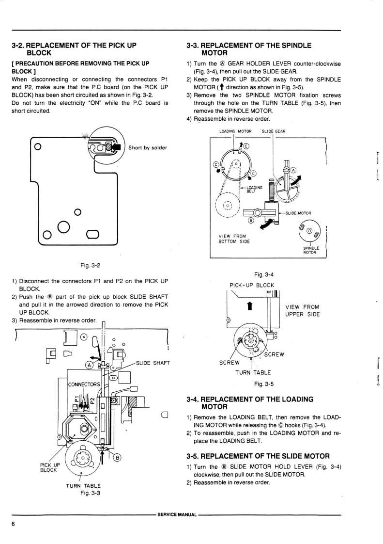
3-2.REPLACEMENT OF THE PICK UP3-3.REPLACEMENT OF THE SPINDLEBLOCKMOTORPRECAUTION BEFORE REMOVING THE PICK UP1)Turn the GEAR HOLDER LEVER counter-clockwiseBLOCK](Fig.3-4),then pull out the SLIDE GEARWhen disconnecting or connecting the connectors P12)Keep the PICK UP BLOCK away from the SPINDLEand P2.make sure that the P.C board (on the PICK UPMOTOR(↑direction as shown in Fig..3-5)】BLOCK)has been short circuited as shown in Fig.3-2.3)Remove the two SPINDLE MOTOR fixation screwsDo not turn the electricity "ON"while the P.C board isthrough the hole on the TURN TABLE (Fig.3-5),thenshort circuited.remove the SPINDLE MOTOR.4)Reassemble in reverse order.LOADING MOTORSLIDE GEARShort by soldert©SLIDE MOTOR⊙VIEW FROMBOTTOM SIDEFig.3-2Fig.3-41)Disconnect the connectors P1 and P2 on the PICK UPBLOCK.PICK-UP BLOCK2)Push the part of the pick up block SLIDE SHAFTeand pull it in the arrowed direction to remove the PICKVIEW FROMUP BLOCK.UPPER SIDE3)Reassemble in reverse order.0SCREWA RUSLIDE SHAFTSCREWTURN TABLECONNECTORSFig.3-53-4.REPLACEMENT OF THE LOADINGMOTOR1)Remove the LOADING BELT,then remove the LOAD-ING MOTOR while releasing the C hooks(Fig.3-4).2)To reassemble,push in the LOADING MOTOR and re-place the LOADING BELT.B3-5.REPLACEMENT OF THE SLIDE MOTORPICK UPBLOCK1)Turn the SLIDE MOTOR HOLD LEVER (Fig.3-4)clockwise,then pull out the SLIDE MOTOR.TURN TABLE2)Reassemble in reverse order.Fig.3-3SERVICE MANUAL

请登录后查看评论内容