
第1页 / 共58页
第2页 / 共58页
第3页 / 共58页
第4页 / 共58页
第5页 / 共58页
试读已结束,还剩53页,您可下载完整版后进行离线阅读
THE END
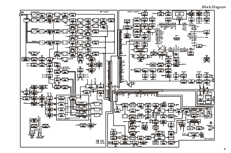
50/144/430 MHz Triple-BandVERTEX STANDARD CO.,LTD.4-8-8 Nakaregu.Meguro-Ku,Tokyo153-8644.JapanVERTEX STANDARDHeavy Duty Submersible TransceiverUS Headquarters10900 Walker Steet,Cypress,CA 90630,U.SA.In ternational DivisionVX-7R8350 N.W.52nd Terrace,Sute 201,Miami,FL 33166,U.S.A.YAESU EUROPE B.V.P.O.Box 75525,1118 ZN Schiphol,The NetherlandsYAESU UK LTD.Technical SupplementWine ameVERTEX STANDARD HK LTD.@2002 VERTEX STANDARD CO.,LTD.Printed in Japan.EH0O9M90AIntroductionThis manual provides the technical information necessary for servicingthe VX-7R 50/144/430 MHZTriple-Band Heavy Duty Submersible Trans-ceiver.Servicing thisequipment requires expertise in handing surface-mountchip components.Attempts by non-qualified persons to service thisequipment may result in permanent damage not covered by the war-ranty,and may be illegal in some countries.Two PCB layout diagrams provided for each double-sided board inthis transceiver.Each side of the board is referred to by the type of themajority of components installed on that side ("Side A"or"Side B").Inmost cases one side hasonly chip components,and the other has eithera mixture of both chip and leaded components(trimmers,coils,electro-CANND Dlytic capacitors,ICs,etc.),or leaded components only.1R正While we believe the information in this manual to be correct,VER-TEX STANDARD assumes no liability for damage that may occur as a7result of typographical or other errors that may be present.Your coop-eration in pointing out any inconsistencies in the technical informationwould be appreciated.ContentsSpecification.2Exploded View Miscellaneous Parts..............4Block Diagram.…5Interconnection Diagram..6Circuit Description…Alignment….11Board Unit(Schematics,Layouts Parts)RF Unit............19AF Unit…33CNTL Unit…43VCO Unit...53


请登录后查看评论内容