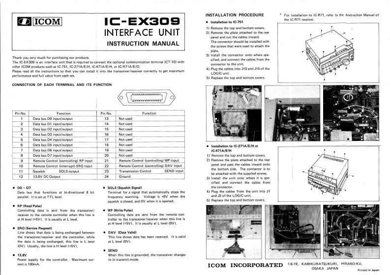
INSTALLATION PROCEDUREFor iretallation to IC-R71.refer so the Instruction Manual ofICOMIG-EX3▣9Installation to IC-751the IC-R71 racxiwer.1]Remowe the top and bottom covers.INTERFACE UNIT2]Ramowe the plate attached to the reorpanel ind run the cobles inward.INSTRUCTION MANUALThe connector should be irstalled with边eow5htgr用dte时tach theplate.3引Install the connec时or anto where ipeThank you very much for purchasing our products.The IC-EX309 is in intertace unit that is roguired to eonnoet the optional communication terminal (CT-10)withcified,and connect the cables from theother ICOM products such as IC-751.IC-271A/E/H.IC-471A/E/H,er IC-R71A/E/D.connecter to the unit.Please read all the instructions so that you can install it into the transciver/reeaiver correetly to get maximum4)Plup the cables into J10 and J15 of theand full walue from each set.LOGIC unit.5]Raplace the top and bottom cowers.CONNECTION OF EACH TERMINAL AND ITS FUNCTIONALRU机UPin No.FunctionPin No.1Data hus DO ingut/output13Not used2Data bus D1 input/output14Not used3Data bus D2 input/output15Not updData bus D3 input/output16Not usodData bus D4 input/output17Not used6Data bus D5 input/output18Not upadInstallation to IC-271A/E/H or7Dats bus D8 input/output19Not usodIC-471A/E/H8Data bus D7 input/output20Not used1)Remove the top and bottom cowers.9Remote Control (controllingl RP input21Remote Control (controlling)WP input21 Remowe the plate attached to the rearRemote Control (interrupt)SRO input22Remote Contrel (eantrollingl DAV inputpanel and pass the cables inward anto11SquelchSOLS output23Transmission ControlSEND inputthe bottom side.The connestor is tobe attached with the suppli悟doew得13.8V DC Output24Ground3)Irstall the unit onto where it i specified and connect the cables from.DO~D7·s0Lssq.elch S5naIt价a connector,Data bus that functions at bi-directional 8 bitTerminal for a signal that automatically stops the4)Plug the cables from the unit into J1网rael.It is set at TTL levefrequeney seinning Voltape is 48V when theand J3 of the LOGIC unit.squelch is cloned,and O when it is openod.5)Replace tha top and bottom covers.RP (Read Pulse)Controlling data is sont from the transesiver/.WP (Write Pulse)receiver to tha remote controller when this line isControlling dota are sent from the remele conat H level |+5V).It is uwaally at L lereel.troller to the trarsceher/receiver when this line isat H lew[t5V门,It is uwally at L level (OV.SRO (Servics RequestlLine shows that data is being exxchanped between●DAV (Data Valid]the transeeivar/recaiver and the controller,whieThis line shows data has been reoeied It is walid中atu珠being ex中anged.this li时i博L levelat L level IOVI.(0V)Usually,the line is H level (+5V).·SEND◆13.8VWhen this line is grounded.the trangceiver chengasPowir wupply for the controller.Maximum cur-to in trarsmit mode.rent is 100mA.ICOM INCORPORATED 1618.KAMIKURATSUKURI.HIRANO-KU.OSAKA JAPANni对pn


请登录后查看评论内容