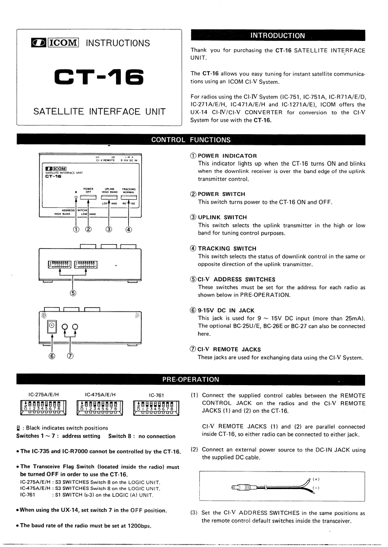
INTRODUCTIONICOM INSTRUCTIONSThank you for purchasing the CT-16 SATELLITE INTERFACEUNIT.CT-16The CT-16 allows you easy tuning for instant satellite communica-tions using an ICOM CI-V System.For radios using the CI-IV System (IC-751.IC-751A,IC-R71A/E/D,IC-271A/E/H,IC-471A/E/H and IC-1271A/E),ICOM offers theSATELLITE INTERFACE UNITUX-14 CI-IV/CI-V CONVERTER for conversion to the CI-VSystem for use with the CT-16.CONTROL FUNCTIONSvEo段g5VoEw①POWER INDICATORThis indicator lights up when the CT-16 turns ON and blinksCOMwhen the downlink receiver is over the band edge of the uplinktransmitter control.②POWER SWITCHThis switch turns power to the CT-16 ON and OFF.③UPLINK SWITCH①②This switch selects the uplink transmitter in the high or low③④band for tuning control purposes.④TRACKING SWITCHThis switch selects the status of downlink control in the same or即马opposite direction of the uplink transmitter.⑤CI-V ADDRESS SWITCHESThese switches must be set for the address for each radio as⑤shown below in PRE-OPERATION.⑥9-15 DC IN JACKThis jack is used for 9~15V DC input (more than 25mA).回99The optional BC-25U/E,BC-26E or BC-27 can also be connectedhere.⑦CI-V REMOTE JACKS7These jacks are used for exchanging data using the Cl-V System.PRE-OPERATIONIC-275A/E/HIC-475A/E/H1C-761(1)Connect the supplied control cables between the REMOTEg男用g日明gggCONTROL JACK on the radios and the CI-V REMOTEUDDO0OuUouobuuJACKS (1)and (2)on the CT-16.日:Black indicates switch positionsCI-V REMOTE JACKS (1)and (2)are parallel connectedSwitches 1~7:address setting Switch 8:no connectioninside CT-16,so either radio can be connected to either jack..The IC-735 and IC-R7000 cannot be controlled by the CT-16.(2)Connect an external power source to the DC-IN JACK usingthe supplied DC cable.The Transceive Flag Switch (located inside the radio)mustbe turned OFF in order to use the CT-16.IC-275A/E/H S3 SWITCHES Switeh 8 on the LOGIC UNIT.(+)IC-475A/E/H S3 SWITCHES Switch 8 on the LOGIC UNIT.m一一;1C-761S1 SWITCH (s-3)on the LOGIC (A)UNIT..When using the UX-14,set switch 7 in the OFF position.(3)Set the Cl-V ADDRESS SWITCHES in the same positions asthe remote control default switches inside the transceiver..The baud rate of the radio must be set at 1200bps.


请登录后查看评论内容