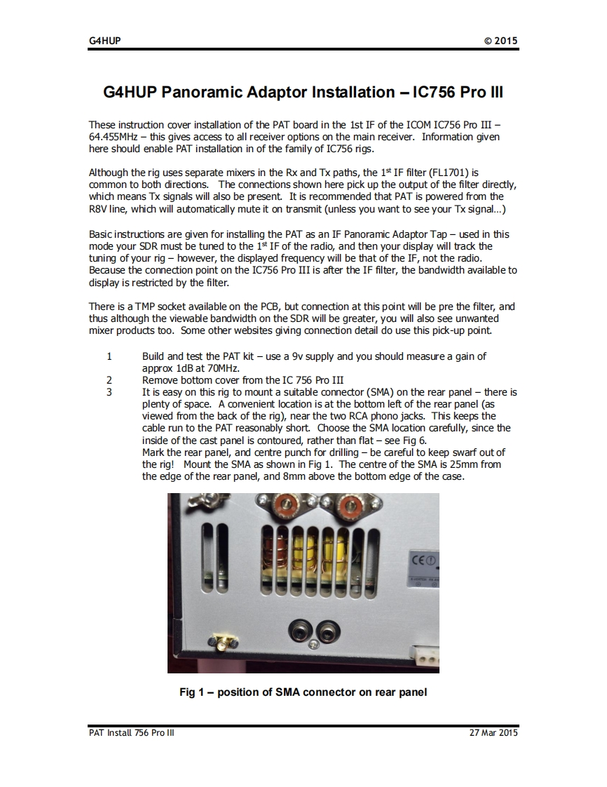
G4HUP©2015G4HUP Panoramic Adaptor Installation-IC756 Pro lllThese instruction cover installation of the PAT board in the 1st IF of the ICOM IC756 Pro III-64.455MHz this gives access to all receiver options on the main receiver.Information givenhere should enable PAT installation in of the family of IC756 rigs.Although the rig uses separate mixers in the Rx and Tx paths,the 1st IF filter(FL1701)iscommon to both directions.The connections shown here pick up the output of the filter directly,which means Tx signals will also be present.It is recommended that PAT is powered from theR8V line,which will automatically mute it on transmit (unless you want to see your Tx signal...)Basic instructions are given for installing the PAT as an IF Panoramic Adaptor Tap-used in thismode your SDR must be tuned to the 1st IF of the radio,and then your display will track thetuning of your rig-however,the displayed frequency will be that of the IF,not the radio.Because the connection point on the IC756 Pro III is after the IF filter,the bandwidth available todisplay is restricted by the filter.There is a TMP socket available on the PCB,but connection at this point will be pre the filter,andthus although the viewable bandwidth on the SDR will be greater,you will also see unwantedmixer products too.Some other websites giving connection detail do use this pick-up point.1Build and test the PAT kit-use a 9v supply and you should measure a gain ofapprox 1dB at 70MHz.2Remove bottom cover from the IC 756 Pro III3It is easy on this rig to mount a suitable connector(SMA)on the rear panel-there isplenty of space.A convenient location is at the bottom left of the rear panel (asviewed from the back of the rig),near the two RCA phono jacks.This keeps thecable run to the PAT reasonably short.Choose the SMA location carefully,since theinside of the cast panel is contoured,rather than flat-see Fig 6.Mark the rear panel,and centre punch for drilling-be careful to keep swarf out ofthe rig!Mount the SMA as shown in Fig 1.The centre of the SMA is 25mm fromthe edge of the rear panel,and 8mm above the bottom edge of the case.C①Fig 1-position of SMA connector on rear panelPAT Install 756 Pro Ill27Mar2015


请登录后查看评论内容