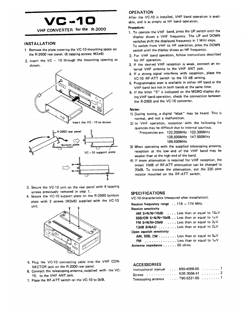
OPERATIONVC-10After the VC-10 is installed,VHF band operation is avail-able,and is as simply as HF band operation.VHF CONVERTER for the R-2000Procedure:1.To operate the VHF band,press the UP switch until thedisplay shows a VHF frequency.The UP and DOWNINSTALLATIONswitches shift the displayed frequency in 1 MHz steps.To switch from VHF to HF operation,press the DOWN1.Remove the plate covering the VC-10 mounting space onswitch until the display shows an HF frequency.the R-2000 rear panel.(6 tapping screws:M3x6)2.For VHF band operation,follow instructions described2.Insert the VC-10 through the mounting opening asfor HF operation.shown.3.If the desired VHF reception is weak,connect an ex-ternal VHF antenna to the VHF ANT jack.4.If a strong signal interferes with reception,place theVC-10 RF-ATT switch to the 10 dB setting.05.Programmable scan is available in either HF band or theVHF band but not in both bands at the same time.6.If the letter "E"is indicated on the MEMO display dur-ing VHF band operation,check the connection betweenthe R-2000 and the VC-10 converter.Notes:1)During tuning,a digital "click"may be heard.This isnormal,and not a malfunction.Insert the VC-10 as shown2)In VHF operation,reception'with the following fre-quencies may be difficult due to internal spurious.R-2000 rear paneFrequencies are:122.200MHz 122.300MHz128.500MHz147.500MHz166.500MHzBottom p3)When operating with the supplied telescoping antenna,VC-10 support platereception at the low end of the VHF band may beweaker than at the high end of the band.4)If more attenuation is required for VHF reception,thepreset 10dB of RF-ATT attenuation can be changed to20dB.To increase the attenuation,cut the 220 ohmresistor mounted on the RF-ATT switch.3.Secure the VC-10 unit on the rear panel with 6 tappingscrews previously removed in step 1.4.Secure the VC-10 support plate on the R-2000 bottomSPECIFICATIONSVC-10 characteristics (measured after installation).plate with 2 screws (M3x6)supplied with the VC-10unit.Receive frequency range .118-174 MHzReceive sensitivityAM S+N/N=10dB ...Less than or equal to 10uVSSB/CW S+N/N=10dB .Less than or equal to 1VFM S+N/N=20dB···Less than or equal to2rV12dB SINAD........Less than or equal to 2uvOpen squelch sensitivityAM,SSB,CW.·.·.·.Less than or equal to5uVFM·.·,.,.·..Le5 s than or equal to1uVAntenna impedance......50 ohms5.Plug the VC-10 connecting cable into the VHF CON-NECTOR jack on the R-2000 rear panel.ACCESSORIES6.Connect the telescoping antenna,supplied with the VC.Instructional manual....B50-4058-00........110,to the VHF ANT jack.Screw:5..N35.3006-41.27.Place the RF-ATT switch on the VC-10 to OdB.Telescoping antenna..T90-0331-05....1


请登录后查看评论内容