
第1页 / 共17页
第2页 / 共17页
第3页 / 共17页
第4页 / 共17页
第5页 / 共17页
第6页 / 共17页
第7页 / 共17页
第8页 / 共17页
第9页 / 共17页
第10页 / 共17页
试读已结束,还剩7页,您可下载完整版后进行离线阅读
THE END
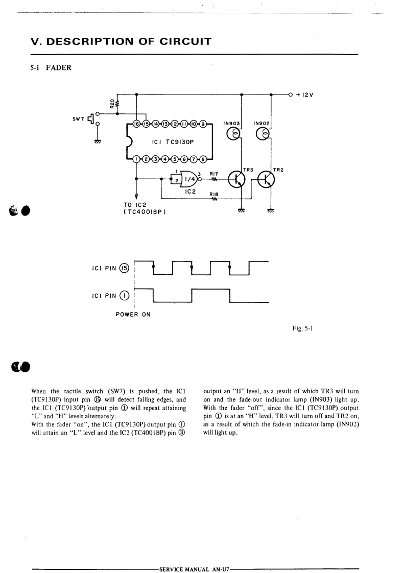
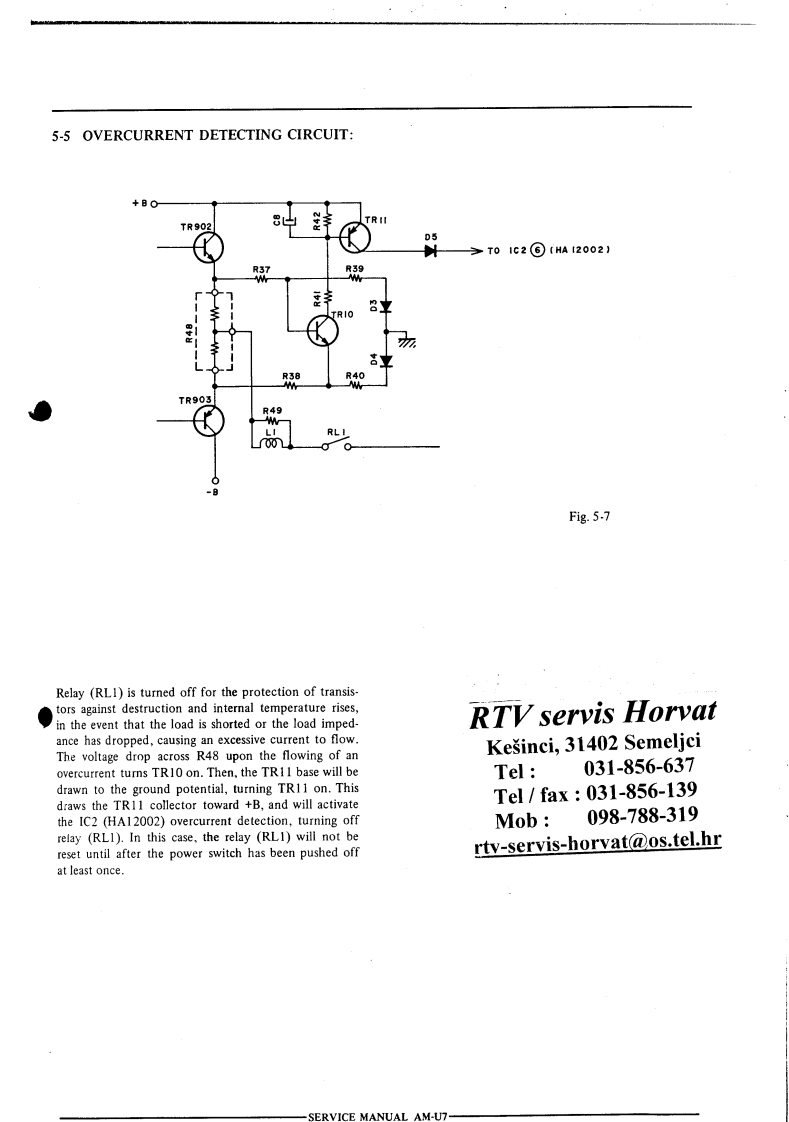
V.DESCRIPTION OF CIRCUIT5-1 FADERO+12V5W7⑥⑥©③②①⊙⑨N903IN902ICI TC9130P-0②③④⑤⑥⑦⑧TR3TR21C2TO IC2色●TC400IBP)ICI PIN⑤ICI PIN 1POWER ONFig.5-1When the tactile switch (SW7)is pushed,the IC1output an"H"level,as a result of which TR3 will turn(TC9130P)input pin 13 will detect falling edges,andon and the fade-out indicator lamp (IN903)light up.the ICI (TC9130P)output pin 1 will repeat attainingWith the fader "off",since the ICI (TC9130P)output“L”and“H"levels alternately..pin①is at an“H'level,TR3 will turn off and TR2onWith the fader "on",the IC1 (TC9130P)output pin 1as a result of which the fade-in indicator lamp (IN902)will attain an "L"level and the IC2(TC4001BP)pin 3will light up.SERVICE MANUAL AM-U7-


请登录后查看评论内容