
第1页 / 共17页
第2页 / 共17页
第3页 / 共17页
第4页 / 共17页
第5页 / 共17页
第6页 / 共17页
第7页 / 共17页
第8页 / 共17页
第9页 / 共17页
第10页 / 共17页
试读已结束,还剩7页,您可下载完整版后进行离线阅读
THE END
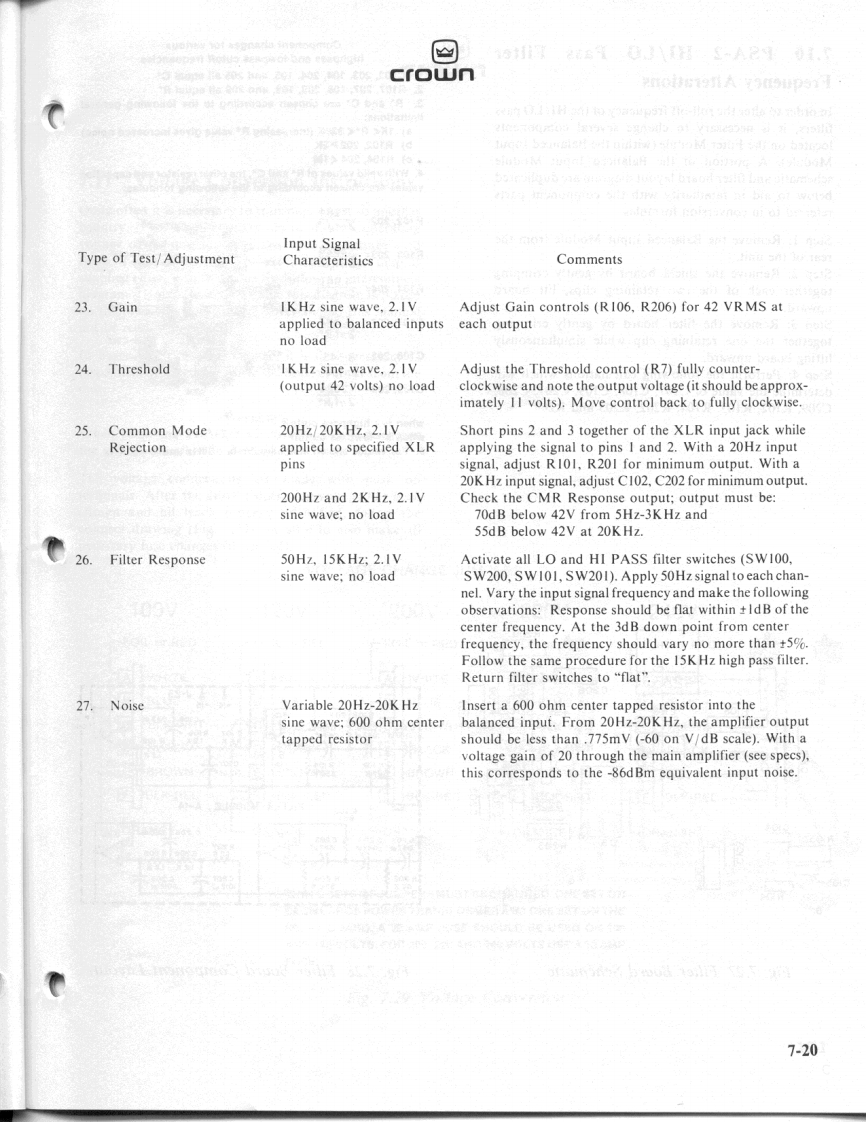
回crownInput SignalType of Test/AdjustmentCharacteristicsCommentsMultiplier BalanceC.100Hz sineC.This adjustment must be made if and only if the protec-wave:variabletion circuitry (steps 11A.B)is not functioning properly.(no load)Apply the input signal to full output(without a load)with-out clipping the signal.Adjust R124 and R224 for minimumsignal null at test pins 1,2,3 and 4 on main board module(scope should be set at 100mV for proper viewing).Repeatsteps IIA,B:proceed to step I1D.Temperature ComputerD.10Hz sineD.Measure the AC voltage across C112,C212.C113,wave;30V outputC213,C114 and C214 with a true RMS meter.This may belevel with 4 ohmdone by measuring across the proper pins of RN103,RN203load(see schematic).Across:C112/C212 measure.4VAC t10C113/213 measure 1.7VAC +10%C114/214 measure.036 +10%If these measurements cannot be obtained,a problemexists in the thermal computer circuitry.12.Anti-pop CircuitIKHz sine wave;Observe the output of pins M and U on the Main(earlier PSA-2/2Vno loadModule while turning the unit on and off several times.ASA units have thisspike should be noticable upon each turn-on.circuit on separateObserve the signals at the output terminals.They shouldmodule.Later ampsnot exhibit any spike during turn-on.include this circuit onMain Module).13.Display ModuleA.IKHz sineA.Increase input level until the green"Signal"presence(PSA-2/PSA-2X)wave;variableindicators illuminate.The voltage level should be approx-no loadimately 1.2 volts peak at the output.Connect an oscilliscopeto the amplifier output.Again raise the input level to thepoint just before clipping is observed.Note the IOCindicators;they should illuminate prior to the visible clip-ping point on the scope.Display ModuleB.IKHz sineB.Vary input level,noting upward progression ofSA2/PSA-2Dwave;variableladder display proportional to the input signal variance.PSA-2DX)no loadConnect an oscilliscope to the amplifier output.Raise theinput level to the point just before clipping is observed.Note the IOC indicators,they should illuminate prior tothe visible clipping point on the scope.14.PowerA.IK Hz sine wave,A.44V minimum should be obtainable before clip.2Vrms;8 ohm loadB.IKHz sine wave,B.20V minimum should be obtainable before clip.2V;8 ohm and induc-tive (159uh)loadC.IKHz sine wave.C.41V minumum should be obtainable before clip.2V;4 ohm load7-16


请登录后查看评论内容