
第1页 / 共4页
试读已结束,还剩3页,您可下载完整版后进行离线阅读
THE END
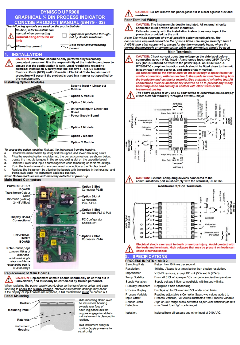
DYNISCO UPR900CAUTON:Do not remove the panel gasket;it is a seal against dust andGRAPHICAL DIN PROCESS INDICATORmoisture.Rear Terminal WiringCONCISE PRODUCT MANUAL(59479-02)The following symbols are used on the product labels:CAUTION:The instrument is double insulated.All external circuitsconnected must provide double insulation.Caution,refer to installationmanual when connectingFailureto comply with the installation instructions may impact theEquipment protected through-protection provided by the unit.General danger to life orut by double insulatonNote:The wiring diagrams show al possible option combinations.Theimbctions required depend on the options fitted.Use single strand(1.2mmAlternating currentBoth direct and alternatingAWG18 max size)copper wire,except for the thermocouple input,where thecurrentcorrect themmocouple or compensating cable and connectors should be used.Main TerminalsINSTALLATIONCAUTION:Installation should be only performed by technicallyCAUTION:Check correct operating voltage on the side label beforeconnectingrge fuse.rated 250V (for AC)competent personnel.It is the respons ibility of the installing engineer to65V(for DC)should be fitted to the power input.An IEC60947-1ensure that the configuration is safe.Local regulations regardingIEC60947-3 compliant isolation switch should be fitted close to the unit.electrical installation safety must be observed-e.g.US Nationalin easy reach of the operator,and aElectrical Code (NEC)and/or Canadian Electrical Code.Impaiment ofconetins to the device mus format orprotection will occur if the product is used in a manner not specified bysimilar connection,with connection to the spade terminal touching boththe manufacturer.the insulation and conductor material.(Use a standard crimping tool)AllInstalling Option Modulesconnections must be Mechanically secured so as to prevent any wirngSecond Input+Linear outbecoming loose and coming in contact with other wires or theModuleinstrument casingThe above aapplies to anyand all connection toardousmains supplyOption A Moduleeither direct or indirect (Through a switch(Relay))Option 3 ModuleUniversal Input+Linear outBoardPower Supply Board8MOption 1 ModuleOption 2 Module:}1Option C ModuleTo acoe ss the option modules,first pullthe instrument from the housing.Detach the main boards by lifting first the upper,and lower mounting strutsPlug the required option modules into the correct connectors,as shown below.cLocate the module tongues in the corresponding slot on the oppo site board.Hold the Power and Input boards together while relocating on their mountingsPush the boards forward to ensure correct connection to the Display board.OPTION 2fReplace the instrument by aligning the boards with the guides in the housing,andthen slowly push he instrument back into posifion.Note:Option modules are automatically detected at power up.Main Board ConnectorsCAUTION:External computing devices connected to thecommunications port must comply with the standard,UL 60950.PO

请登录后查看评论内容