
第1页 / 共20页
试读已结束,还剩19页,您可下载完整版后进行离线阅读
THE END
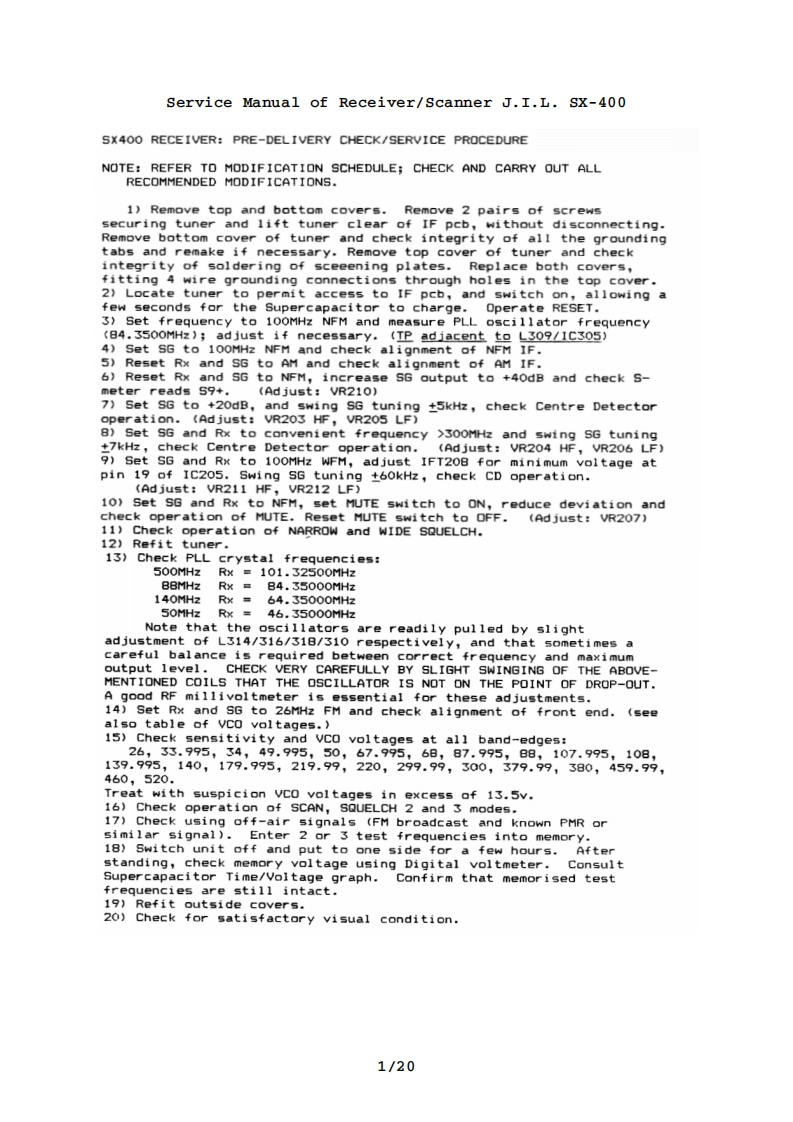
Service Manual of Receiver/Scanner J.I.L.SX-400SX400 RECEIVER:PRE-DELIVERY CHECK/SERVICE PROCEDURENOTE:REFER TO MODIFICATION SCHEDULE:CHECK AND CARRY OUT ALLRECOMMENDED MODIFICATIONS.1)Remove top and bottom covers.Remove 2 pairs of screwssecuring tuner and lift tuner clear of IF pcb,without disconnecting.Remove bottom cover of tuner and check integrity of all the groundingtabs and remake if necessary.Remove top cover of tuner and checkintegrity of soldering of sceeening plates.Replace both covers,fitting 4 wire grounding connections through holes in the top cover.2)Locate tuner to permit access to IF pcb,and switch on,allowing afew seconds for the Supercapacitor to charge.Operate RESET.3)Set frequency to 100MHz NFM and measure PLL oscillator frequency(84.3500MHz);ad just if necessary.(TP adiacent to L309/1C305)4)Set SG to 100MHz NFM and check alignment of NFM IF.5)Reset Rx and SG to AM and check alignment of AM IF.6)Reset Rx and SG to NFM,increase SG output to +40dB and check S-meter reads 59+.(Ad just:VR210)7)Set SG to +20dB,and swing SG tuning t5kHz,check Centre Detectoroperation.(Ad just:VR203 HF,VR205 LF)8)Set S6 and Rx to convenient frequency >300MHz and swing SG tuning+7kHz,check Centre Detector operation.(Ad just:VR204 HF,VR206 LF)9)Set SG and Rx to 100MHz WFM,adjust IFT208 for minimum voltage atpin 19 of IC205.Swing SG tuning t60kHz,check CD operation.(Ad just:VR211 HF,VR212 LF)10》Set SG and Rx to NFM,set MUTE switch to ON,reduce deviation andcheck operation of MUTE.Reset MUTE switch to OFF.(Adjust:VR207)11)Check operation of NARROW and WIDE SQUELCH.12)Refit tuner.13)Check PLL crystal frequencies:500MHzRx=101.32500MHzB8MHzRx=84.35000MHz140MHzRx64.35000MHz50MHz Rx46.35000MHzNote that the oscillators are readily pulled by slightadjustment of L314/316/318/310 respectively,and that sometimes acareful balance is required between correct frequency and maximumoutput level.CHECK VERY CAREFULLY BY SLIGHT SWINGING OF THE ABOVE-MENTIONED COILS THAT THE OSCILLATOR IS NOT ON THE POINT OF DROP-OUT.A good RF millivoltmeter is essential for these adjustments.14)Set Rx and SG to 26MHz FM and check alignment of front end.(seealso table of VCO voltages.)15)Check sensitivity and VCO voltages at all band-edges:26,33.995,34,49.995,50,67.995,68,87.995,88,107.995,108,139.995,140,179.995,219.99,220,299.99,300,379.99,380,459.99,460,520.Treat with suspicion VCO voltages in excess of 13.5v.16)Check operation of SCAN,SQUELCH 2 and 3 modes.17)Check using off-air signals (FM broadcast and known PMR orsimilar signal).Enter 2 or 3 test frequencies into memory.18)Switch unit off and put to one side for a few hours.Afterstanding,check memory voltage using Digital voltmeter.ConsultSupercapacitor Time/Voltage graph.Confirm that memorised testfrequencies are still intact.19)Refit outside covers.20)Check for satisfactory visual condition.1/20

请登录后查看评论内容