
第1页 / 共3页
试读已结束,还剩2页,您可下载完整版后进行离线阅读
THE END
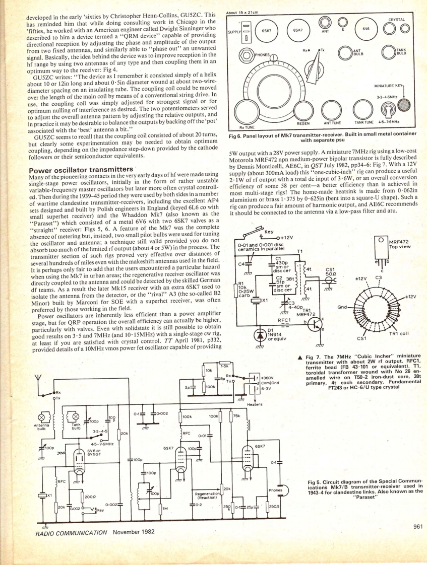
developed in the early 'sixties by Christopher Henn-Collins,GUSZC.ThisAbout 15 x 21cmCRYSTALhas reminded him that while doing consulting work in Chicago in the'fifties,he worked with an American engineer called Dwight Sinninger who65Kdescribed to him a device termed a "'QRM device"'capable of providingdirectional reception by adjusting the phase and amplitude of the outputfrom two fixed antennas,and similarly able to "phase out''an unwantedsignal.Basically,the idea behind the device was to improve reception in thehf range by using two antennas of any type and then coupling them in anoptimum way to the receiver:Fig 4.GUSZC writes:"The device as I remember it consisted simply of a helixabout 10 or 12in long and about 0.5in diameter wound at about two-wirediameter spacing on an insulating tube.The coupling coil could be movedMINIATURE KEY-over the length of the main coil by means of a conventional string drive.In3-3.45MHzuse,the coupling coil was simply adjusted for strongest signal or foroptimum nulling of interference as desired.The two potentiometers servedto adjust the overall antenna pattern by adjusting the relative outputs,andin practice it may be desirable to balance the outputs by backing off the'pot'ANT TUNETANK TUNE4-5-76MHzassociated with the 'best'antenna a bit."RK TUNGU5ZC seems to recall that the coupling coil consisted of about 20 turns,Fig 6.Panel layout of Mk7 transmitter-receiver.Built in small metal containerbut clearly some experimentation may be needed to obtain optimumwith separate psucoupling,depending on the impedance step-down provided by the cathodefollowers or their semiconductor equivalents.5W output with a 28V power supply.A miniature 7MHz rig using a low-costMotorola MRF472 npn medium-power bipolar transistor is fully describedPower oscillator transmittersby Dennis Monticelli,AE6C,in OST July 1982,pp34-6:Fig 7.With a 12VMany of the pioneering contacts in the very early days of hf were made usingsupply (about 300mA load)this"'one-cubic-inch''rig can produce a usefulsingle-stage power oscillators,initially in the form of rather unstable2.IW of rf output with a total de input of 3.6W,or an overall conversionvariable-frequeney master oscillators but later more often crystal controll-efficiency of some 58 per cent-a better efficiency than is achieved ined.Then during the 1939-45 period they were used by both sides in a numbermost multi-stage rigs!The home-made heatsink is made from 0.062inof wartime clandestine transmitter-receivers,including the excellent AP4aluminium or brass 1.375 by 0-625in(bent into a square-U shape).Such asets designed and built by Polish engineers in England (keyed 6L6 co withrig can produce a fair amount of harmonic output,and AE6C recommendssmall superhet receiver)and the Whaddon Mk7 (also known as theit should be connected to the antenna via a low-pass filter and atu."Paraset")which consisted of a metal 6V6 with two 6SK7 valves as a"straight"receiver:Figs 5,6.A feature of the Mk7 was the completea

请登录后查看评论内容