
第1页 / 共19页
试读已结束,还剩18页,您可下载完整版后进行离线阅读
THE END
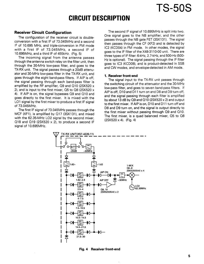
TS-50SCIRCUIT DESCRIPTIONReceiver Circuit ConfigurationThe second IF signal of 10.695MHz is split into two.The configuration of the receiver circuit is double-One signal goes to the NB amplifier,and the otherconversion with a first IF of 73.045MHz and a secondpasses through the NB gate FET (3SK131).The signalIF of 10.695 MHz,and triple-conversion in FM modethen passes through the CF (XF2)and is detected bywith a first IF of 73.045MHz,a second IF ofIC2(KCD04)in FM mode.In other modes,the signal10.695MHz,and a third IF of 455kHz..(Fig.5)goes to the IF filter of the X48-3110-00 unit.There areThe incoming signal from the antenna passesthree types of IF filter:6-kHz,2.7-kHz,and 500-Hz(500-through the antenna switch relay on the filter unit,thenHz is optional).The signal passing through the IF filterthrough the 30-MHz low-pass filter,and goes to thegoes to IC3 (KCD08),and is product-detected in SSBTX-RX unit.The signal passes through a 20dB attenu-and CW modes,and envelope-detected in AM mode.ator and 30-MHz low-pass filter in the TX-RX unit,andgoes through the eight band-pass filters.If AIP is off,1.Receiver front-endthe signal passing through each band-pass filter isThe signal input to the TX-RX unit passes throughamplified by the RF amplifier,Q9 and Q10(2SK520 xthe switching circuit of the attenuator and the 30-MHz2),and is input to the first mixer,Q5 to Q8(2SK520 xlow-pass filter,and goes to seven band-pass filters.If4).If AIP is on,the signal bypasses Q9 and Q10 andAIP is off,D10 and D11 turn on and D8 and D9 turn off,goes directly to the first mixer.It is mixed with theand the signal passing through each filter is amplifiedLO1 signal by the first mixer to produce a first IF signalby about 13 dB by Q9 and Q10(2SK520 x 2)and outputof 73.045MHz.to the first mixer.If AIP is on,D10 and D11 turn off andThe first IF signal of 73.045MHz passes through theD8 and D9 turn on,and the signal is output directly toMCF (XF1),is amplified by Q17 (3SK131),and mixedthe first mixer without passing through Q9 and Q10.with the 62.35-MHz LO2 signal by the second mixer,The first mixer,is a quad balanced mixer,Q5 to Q8Q18 and Q19 (2SK520 x 2),to produce a second IF(2SK520×4).(Fig.4)signal of 10.695MHz.TX-RXUN1T(X57-4220-11)O ATT●-20dB-30MHz1.621.621-MIX05-8AIP ON25K520(K44}X4图AIP OFF-30MHL02Q9.1062.35MHz2SK520K44)×2图14.5-215图21.5-30Fig.4Receiver front-end5

请登录后查看评论内容