
第1页 / 共2页
试读已结束,还剩1页,您可下载完整版后进行离线阅读
THE END
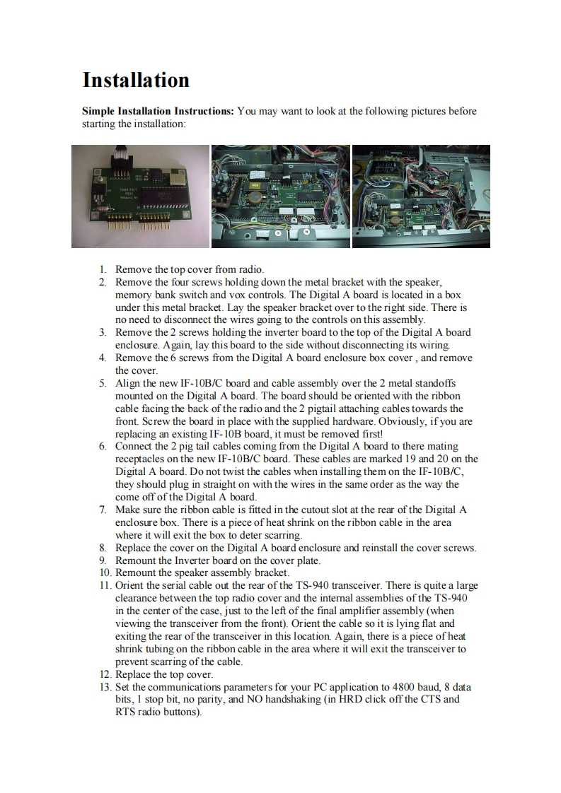
InstallationSimple Installation Instructions:You may want to look at the following pictures beforestarting the installation:117mT1.Remove the top cover from radio.2.Remove the four screws holding down the metal bracket with the speaker.memory bank switch and vox controls.The Digital A board is located in a boxunder this metal bracket.Lay the speaker bracket over to the right side.There isno need to disconnect the wires going to the controls on this assembly.3.Remove the 2 screws holding the inverter board to the top of the Digital A boardenclosure.Again,lay this board to the side without disconnecting its wiring.4.Remove the 6 screws from the Digital A board enclosure box cover,and removethe cover.5.Align the new IF-10B/C board and cable assembly over the 2 metal standoffsmounted on the Digital A board.The board should be oriented with the ribboncable facing the back of the radio and the 2 pigtail attaching cables towards thefront.Screw the board in place with the supplied hardware.Obviously,if you arereplacing an existing IF-10B board,it must be removed first!6.Connect the 2 pig tail cables coming from the Digital A board to there matingreceptacles on the new IF-10B/C board.These cables are marked 19 and 20 on theDigital A board.Do not twist the cables when installing them on the IF-10B/C,they should plug in straight on with the wires in the same order as the way thecome off of the Digital A board.7.Make sure the ribbon cable is fitted in the cutout slot at the rear of the Digital Aenclosure box.There is a piece of heat shrink on the ribbon cable in the areawhere it will exit the box to deter scarring.8.Replace the cover on the Digital A board enclosure and reinstall the cover screws.9.Remount the Inverter board on the cover plate.10.Remount the speaker assembly bracket.11.Orient the serial cable out the rear of the TS-940 transceiver.There is quite a largeclearance between the top radio cover and the internal assemblies of the TS-940in the center of the case,just to the left of the final amplifier assembly (whenviewing the transceiver from the front).Orient the cable so it is lying flat andexiting the rear of the transceiver in this location.Again,there is a piece of heatshrink tubing on the ribbon cable in the area where it will exit the transceiver toprevent scarring of the cable.12.Replace the top cover.13.Set the communications parameters for your PC application to 4800 baud,8 databits,I stop bit,no parity,and NO handshaking (in HRD click off the CTS andRTS radio buttons).


请登录后查看评论内容