
第1页 / 共4页
试读已结束,还剩3页,您可下载完整版后进行离线阅读
THE END
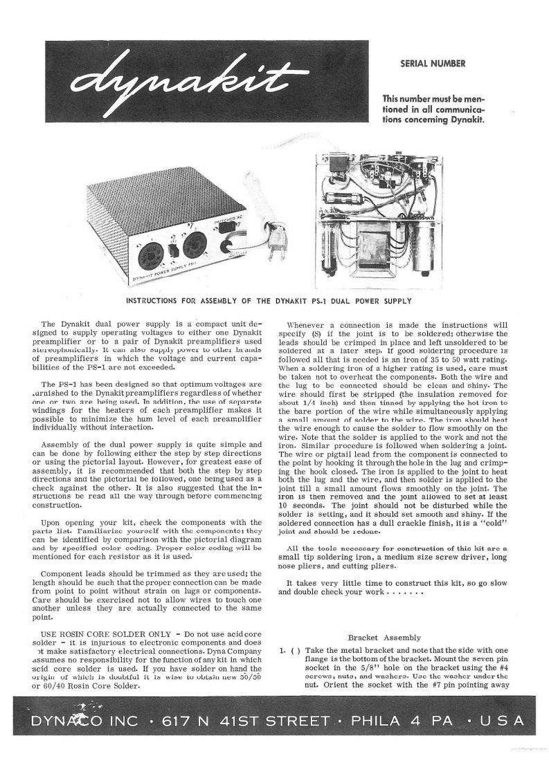
bymakitSERIAL NUMBERThis number must be men-tioned in all communica-tions concerning Dynakit.INSTRUCTIONS FOR ASSEMBLY OF THE DYNAKIT PS-1 DUAL POWER SUPPLYThe Dynakit dual power supply is a compact unit de-Whenever a connection is made the instructions willsigned to supply operating voltages to either one Dynakitspecify (S)if the joint is to be soldered;otherwise thepreamplifier or to a pair of Dynakit preamplifiers usedleads should be crimped in place and left unsoldered to bestereuplouically.It can also supply power to other brandssoldered at a later step.Ir good soldering procedure isof preamplifiers in which the voltage and current capa-followed all that is needed is an iron of 35 to 50 watt rating.bilities of the PS-1 are not exceeded.When a soldering iron of a higher rating is used,care mustbe taken not to overheat the components.Both the wire andThe PS-1 has been designed so that optimum voltages arethe lug to be connccted should be clean and shiny.The.urnished to the Dynakit preamplifiers regardless of whetherwire should first be stripped (the insulation removed forone or two are heing used.In addition,the use of separateabout 1/4 inoh)and then tinned by applying the hot iron towindings for the heaters of each preamplifier makes itthe bare portion of the wire while simultaneously applyingpossible to minimize the hum level of each preamplifiera small amouint of solder to the wire.The iron should heatindividually without interaction.the wire enough to cause the solder to flow smoothly on thewire.Note that the solder is applied to the work and not theAssembly of the dual power supply is quite simple andiron.Similar procedure is followed when soldering a joint.can be done by following either the step by step directionsThe wire or pigtail lead from the component is connected toor using the pictorial layout.However,for greatest ease ofthe point by hooking it through the hole in the lug and crimp-assembly,it is recommended that both the step by steping the hook closed.The iron is applied to the joint to heatdirections and the pictorial be followed,one being used as aboth the lug and the wire,and then solder is applied to thecheck against the other.It is also suggested that the in-joint till a small amount flows smoothly on the joint.Thestructions be read all the way through before commencingron is then removed and the joint allowed to set at leastconstruction.10 seconds.The joint should not be disturbed while thesolder is setting,and it should set smooth and shiny.If theUpon opening your kit,check the components with thesoldered connection has a dull crackle finish,itis a "cold"parta list.Familiarize youroelf with the componcntot theyjoint and should be redone.can be identified by comparison with the pictorial diagramand by speoified oolor ooding.Proper color eoding will beAll the toole nocoeeary for conetruotion of thie kit are amentioned for each resistor as it is used.small tip soldering iron,a medium size screw driver,longnose pliers,and cu

请登录后查看评论内容