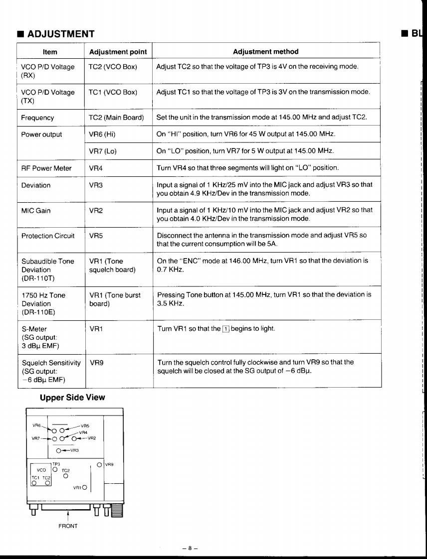
■ADJUSTMENT■BLItemAdjustment pointAdjustment methodVCO P/D VoltageTC2 (VCO Box)Adjust TC2 so that the voltage of TP3 is 4V on the receiving mode.(RX)VCO P/D VoltageTC1 (VCO Box)Adjust TC1 so that the voltage of TP3 is 3V on the transmission mode.(TX)FrequencyTC2 (Main Board)Set the unit in the transmission mode at 145.00 MHz and adjust TC2.Power outputVR6(Hi)On "HI"position,turn VR6 for 45 W output at 145.00 MHz.VR7(Lo)On "LO"position,turn VR7 for 5 W output at 145.00 MHz.RF Power MeterVR4Turn VR4 so that three segments will light on "LO"position.DeviationVR3Input a signal of 1 KHz/25 mV into the MIC jack and adjust VR3 so thatyou obtain 4.9 KHz/Dev in the transmission mode.MIC GainVR2Input a signal of 1 KHz/10 mV into the MIC jack and adjust VR2 so thatyou obtain 4.0 KHz/Dev in the transmission mode.Protection CircuitVR5Disconnect the antenna in the transmission mode and adjust VR5 sothat the current consumption will be 5A.Subaudible ToneVR1(ToneOn the "ENC"mode at 146.00 MHz,turn VR1 so that the deviation isDeviationsquelch board)0.7 KHz.(DR-110T)1750 Hz ToneVR1(Tone burstPressing Tone button at 145.00 MHz,turn VR1 so that the deviation isDeviationboard)3.5 KHz.(DR-110E)S-MeterVR1Turn VR1 so that the begins to light.(SG output:3 dBu EMF)Squelch SensitivityVR9Turn the squelch control fully clockwise and turn VR9 so that the(SG output:squelch will be closed at the SG output of-6 dBu.-6dBμEMF)Upper Side ViewVR5o0+VR4VR7--VR2-VR31TP3vco O rc2TC1 TC2ooVR1OTFRONT-8-

请登录后查看评论内容