
第1页 / 共5页
试读已结束,还剩4页,您可下载完整版后进行离线阅读
THE END
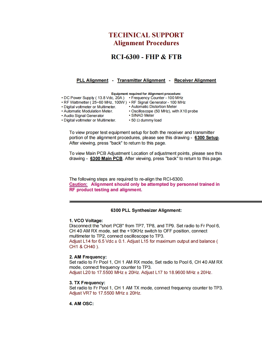
TECHNICAL SUPPORTAlignment ProceduresRCI-6300-FHP FTBPLL Alignment Transmitter AlignmentReceiver AlignmentEquipment required for Alignment procedure:DC Power Supply 13.8 Vdc,20A).Frequency Counter-100 MHz.RF Wattmetter(25~60 MHz,100W).RF Signal Generator-100 MHzDigital voltmeter or MultimeterAutomatic Distortion MeterAutomatic Modulation Meter.Oscilloscope(50 MHz),with X10 probeAudio Signal Generator·SINAD MeterDigital voltmeter or Multimeter.50 dummy loadTo view proper test equipment setup for both the receiver and transmitterportion of the alignment procedures,please see this drawing-6300 Setup.After viewing,press "back"to return to this page.To view Main PCB Adjustment Location of adjustment points,please see thisdrawing-6300 Main PCB.After viewing,press "back"to return to this page.The following steps are required to re-align the RCI-6300.Caution:Alignment should only be attempted by personnel trained inRF product testing and alignment.6300 PLL Synthesizer Alignment:1.VCO Voltage:Disconnect the "short PCB"from TP7,TP8,and TP9.Set radio to Fr Pool 6,CH 40 AM RX mode,set the +10KHz switch to OFF position,connectmultimeter to TP2,connect oscilloscope to TP3.Adjust L14 for 6.5 Vdc+0.1.Adjust L15 for maximum output and balanceCH1&CH40).2.AM Frequency:Set radio to Fr Pool 1,CH 1 AM RX mode,Set radio to Pool 6,CH 40 AM RXmode,connect frequency counter to TP3.Adjust L20 to 17.5500 MHz 20Hz.Adjust L17 to 18.9600 MHz 20Hz3.TX Frequency:Set radio to Fr Pool 1,CH 1 AM TX mode,connect frequency counter to TP3.Adjust VR7 to 17.5500 MHz 20Hz.4.AM OSC:

请登录后查看评论内容