
第1页 / 共10页
试读已结束,还剩9页,您可下载完整版后进行离线阅读
THE END
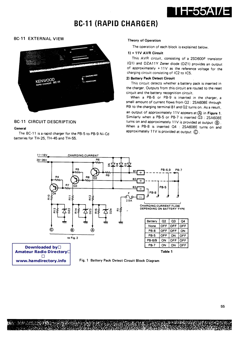
TH-55A17EBC-11 (RAPID CHARGER)BC-11 EXTERNAL VIEWTheory of OperationThe operation of each block is explained below.1)+11V AVR CircuitThis AVR circuit,consisting of a 2SD600F transistor(Q1)and DZA11Y Zener diode (DZ1)provides an outputof approximately +11V as the reference voltage for thecharging circuit consisting of IC2 to IC5.KENWOOD2)Battery Pack Detect CircuitRAPO CHARGERLc-11This circuit detects whether a battery pack is inserted inthe charger.Outputs from this circuit are routed to the resetcircuit and the battery recognition circuit.When a PB-6 or PB-9 is inserted in the charger,asmall amount of current flows from Q2:2SA608E throughR9 to the charging terminal B1 and Q2 turns on.As a result.an output of approximately 11V appears at A in Figure 1.Similarly when a PB-5 or PB-7 is inserted Q3 2SA608EBC-11 CIRCUIT DESCRIPTIONturns on and approximately 11V is provided at output BGeneralWhen a PB-8 is inserted Q4 2SA608E turns on andThe BC-11 is a rapid charger for the PB-5 to PB-9 Ni-Cdapproximately 11V is provided at output Cbatteries for TH-25,TH-45 and TH-55.11~16VCHARGING CURRENT20-26VR68文8立8立R51+P8-6.9PB.7R802M2+]R7038-5PB-825ACHARGING CURRENT FLOWDEPENDING ON BATTERY TYPEBattery Q2 Q3 Q4NoneOFFOFF OFFP8-8OFFOFF ONPB-5 OFF ON OFFto Fig.2P8-6/9ONOFF OFFDownloaded by!▣PB-7 ON ON OFFAmateur Radio DirectoryLTable 1▣www.hamdirectory.infoFig.1 Battery Pack Detect Circuit Block Diagram55

请登录后查看评论内容